Vertex Standard FT-1000MP manual About ALC

Models: FT-1000MP

1 119
Download 119 pages 809 b
Page 15
Image 15

ACCESSORY INSTALLATION

LINEAR AMPLIFIER INTERFACING

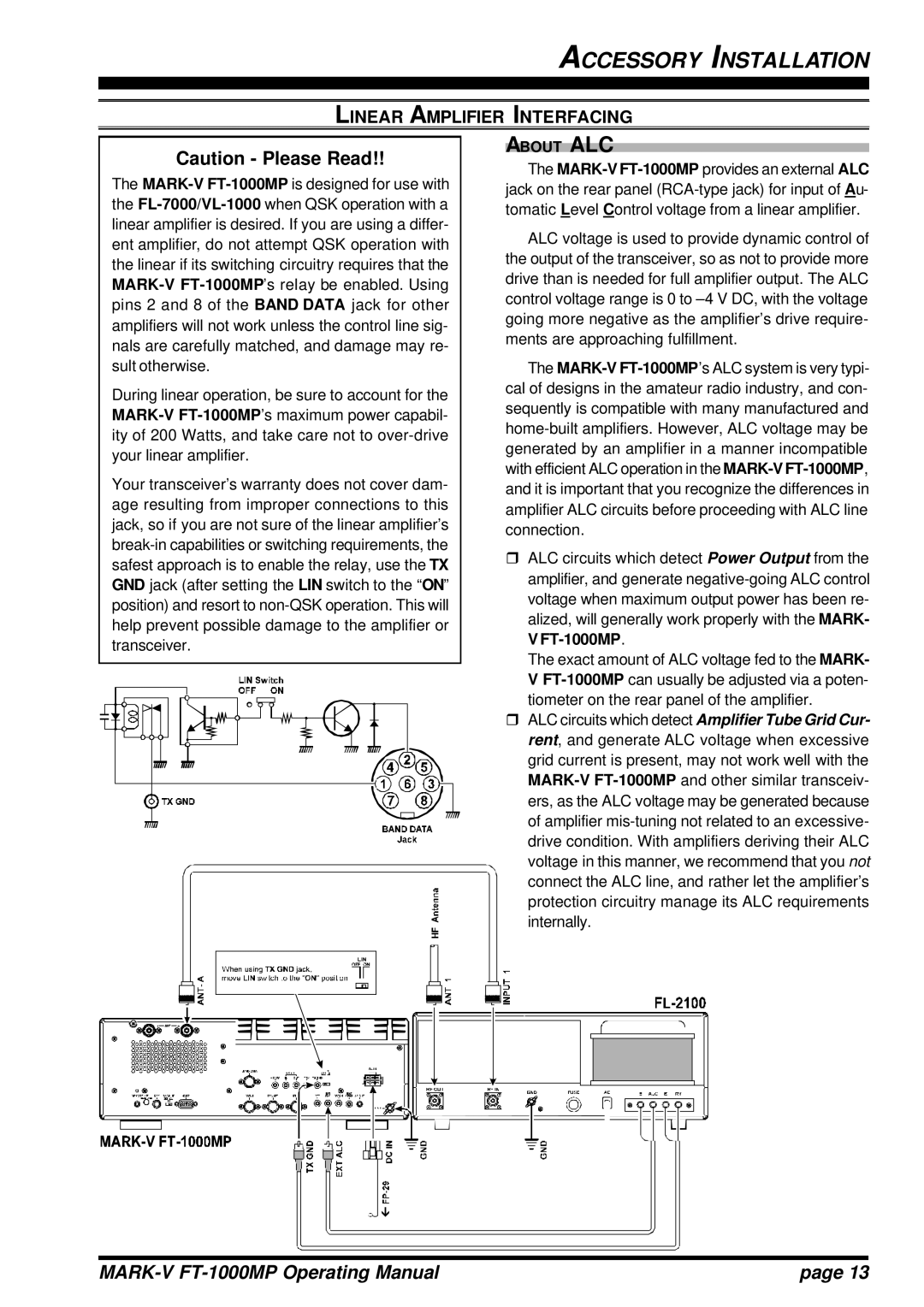
Caution - Please Read!!

The MARK-VFT-1000MPis designed for use with the FL-7000/VL-1000when QSK operation with a linear amplifier is desired. If you are using a differ- ent amplifier, do not attempt QSK operation with the linear if its switching circuitry requires that the MARK-VFT-1000MP’s relay be enabled. Using pins 2 and 8 of the BAND DATA jack for other amplifiers will not work unless the control line sig- nals are carefully matched, and damage may re- sult otherwise.

During linear operation, be sure to account for the MARK-VFT-1000MP’s maximum power capabil- ity of 200 Watts, and take care not to over-drive your linear amplifier.

Your transceiver’s warranty does not cover dam- age resulting from improper connections to this jack, so if you are not sure of the linear amplifier’s break-in capabilities or switching requirements, the safest approach is to enable the relay, use the TX GND jack (after setting the LIN switch to the “ON” position) and resort to non-QSK operation. This will help prevent possible damage to the amplifier or transceiver.

ABOUT ALC

The MARK-VFT-1000MPprovides an external ALC jack on the rear panel (RCA-type jack) for input of Au- tomatic Level Control voltage from a linear amplifier.

ALC voltage is used to provide dynamic control of the output of the transceiver, so as not to provide more drive than is needed for full amplifier output. The ALC control voltage range is 0 to –4 V DC, with the voltage going more negative as the amplifier’s drive require- ments are approaching fulfillment.

The MARK-VFT-1000MP’s ALC system is very typi- cal of designs in the amateur radio industry, and con- sequently is compatible with many manufactured and home-built amplifiers. However, ALC voltage may be generated by an amplifier in a manner incompatible with efficient ALC operation in the MARK-VFT-1000MP, and it is important that you recognize the differences in amplifier ALC circuits before proceeding with ALC line connection.

rALC circuits which detect Power Output from the amplifier, and generate negative-going ALC control voltage when maximum output power has been re- alized, will generally work properly with the MARK- V FT-1000MP.

The exact amount of ALC voltage fed to the MARK- V FT-1000MPcan usually be adjusted via a poten- tiometer on the rear panel of the amplifier.

rALC circuits which detect Amplifier Tube Grid Cur- rent, and generate ALC voltage when excessive grid current is present, may not work well with the MARK-VFT-1000MPand other similar transceiv- ers, as the ALC voltage may be generated because of amplifier mis-tuning not related to an excessive- drive condition. With amplifiers deriving their ALC voltage in this manner, we recommend that you not connect the ALC line, and rather let the amplifier’s protection circuitry manage its ALC requirements internally.

MARK-V FT-1000MP Operating Manual

page 13

Page 15
Image 15
Vertex Standard FT-1000MP manual About ALC