Appendix B Connector and Cable Specifications
Connector Specifications
Dual-Purpose Ports
The 10/100/1000 Ethernet ports on the
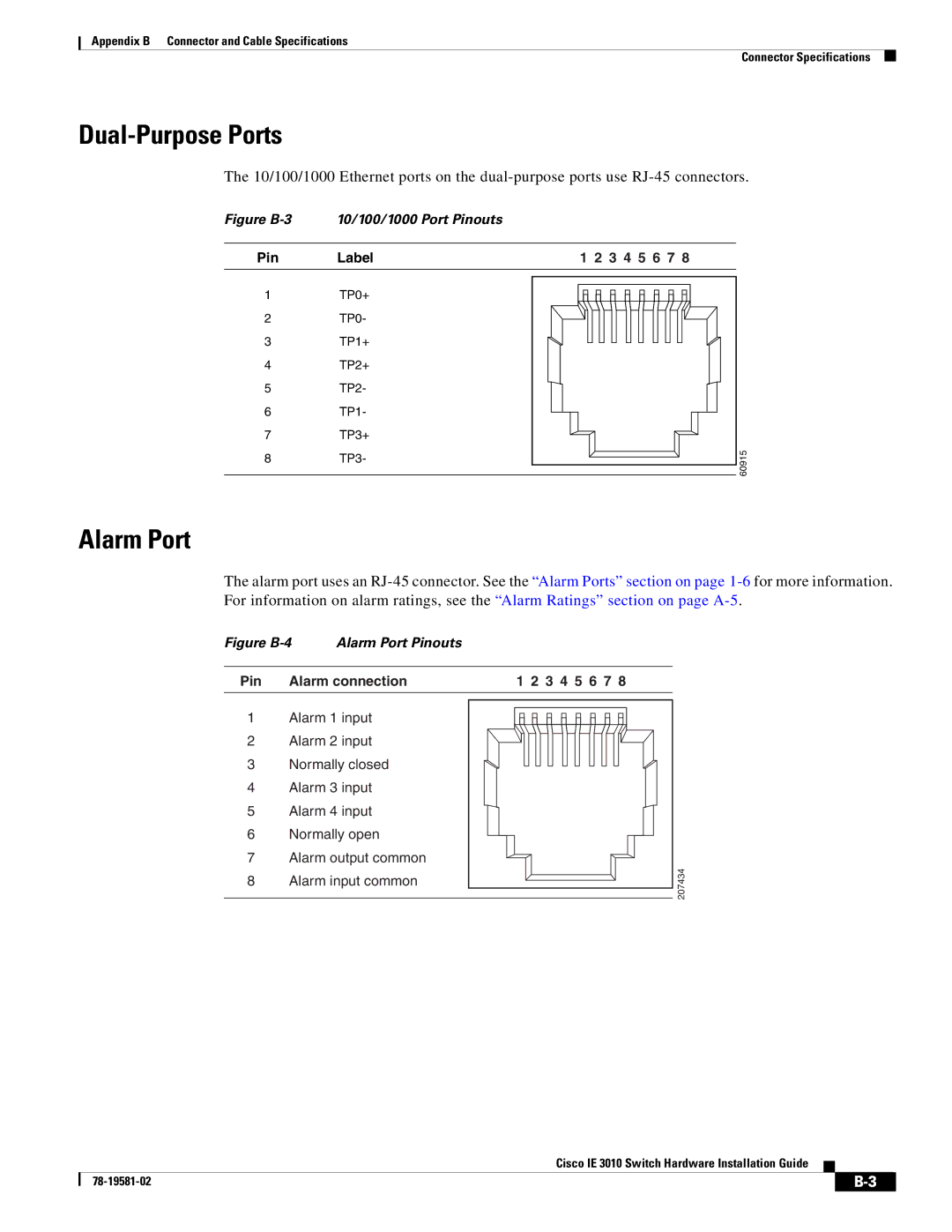
Figure B-3 10/100/1000 Port Pinouts
Pin Label
1TP0+
2TP0-
3TP1+
4TP2+
5TP2-
6TP1-
7TP3+
8TP3-
1 2 3 4 5 6 7 8
60915
Alarm Port
The alarm port uses an
Figure B-4 Alarm Port Pinouts
Pin | Alarm connection |
1Alarm 1 input
2Alarm 2 input
3Normally closed
4Alarm 3 input
5Alarm 4 input
6Normally open
7Alarm output common
8Alarm input common
1 2 3 4 5 6 7 8
207434
Cisco IE 3010 Switch Hardware Installation Guide
| ||
|