Chapter 1 Product Overview
Cable Side
SFP Module Patch Cable
The switch uses an
Figure 1-3 SFP-Module Patch Cable
126809
See the “Inserting and Removing the SFP Module Patch Cable” section on page
You can order this cable (part number
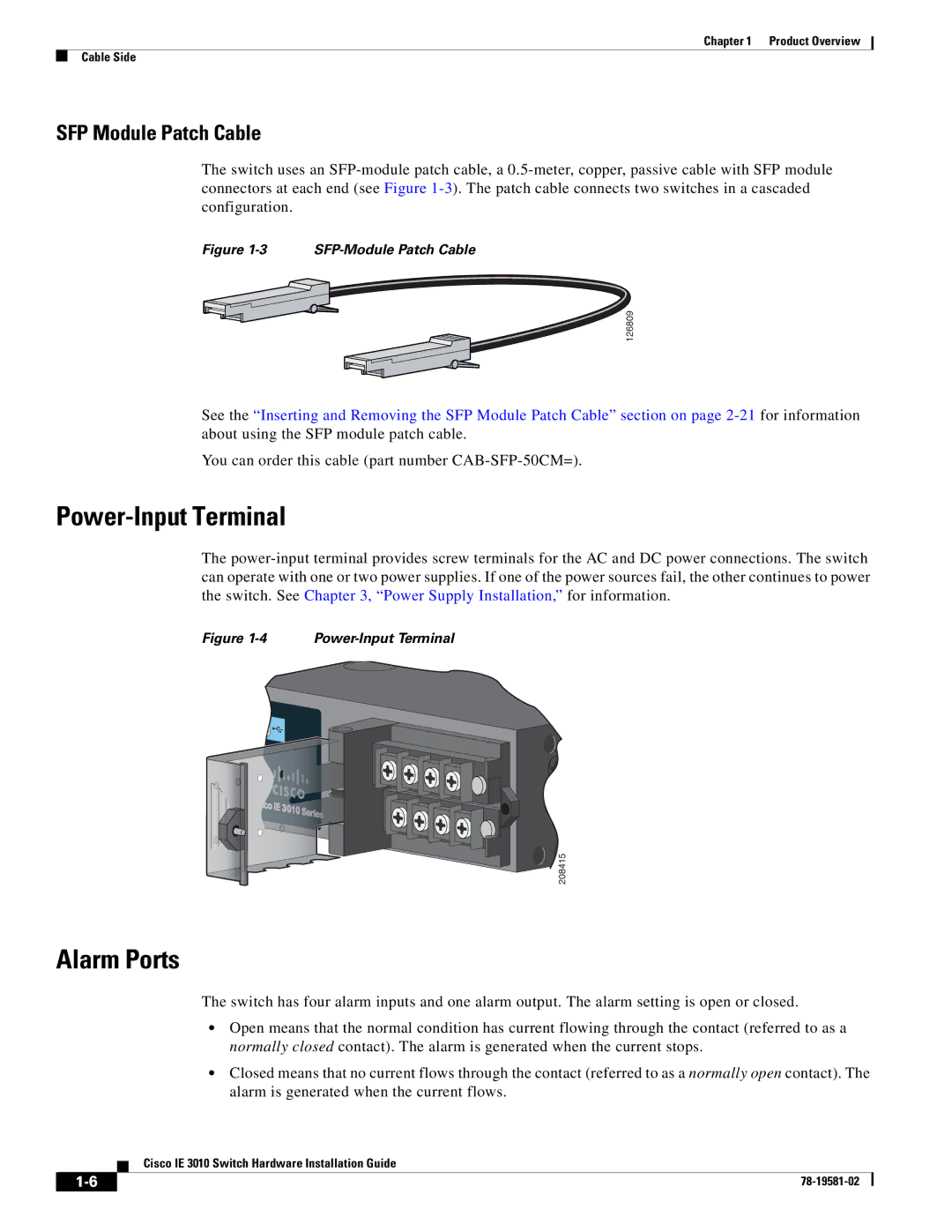
Power-Input Terminal
The
Figure 1-4 Power-Input Terminal
208415
Alarm Ports
The switch has four alarm inputs and one alarm output. The alarm setting is open or closed.
•Open means that the normal condition has current flowing through the contact (referred to as a normally closed contact). The alarm is generated when the current stops.
•Closed means that no current flows through the contact (referred to as a normally open contact). The alarm is generated when the current flows.
Cisco IE 3010 Switch Hardware Installation Guide
| ||
|