Chapter 1 Product Overview
Cable Side
Cable Side
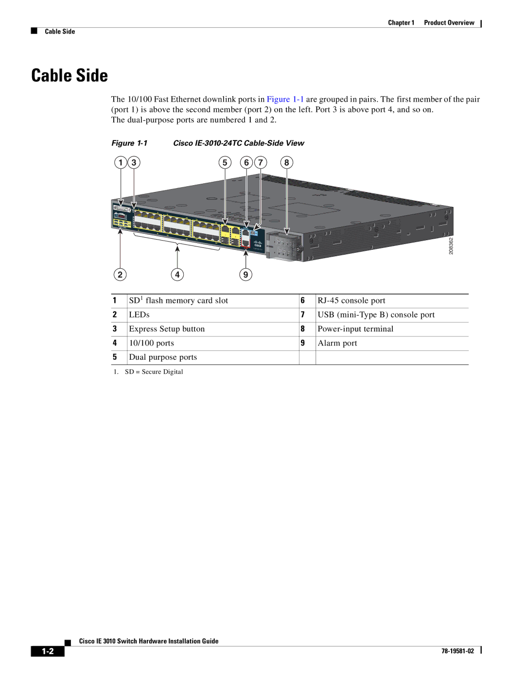
The 10/100 Fast Ethernet downlink ports in Figure
The
Figure 1-1 Cisco IE-3010-24TC Cable-Side View
1 | 3 | 5 | 6 | 7 | 8 |
|
|
|
|
|
|
| 208362 |
|
|
|
|
|
|
| |
|
|
|
|
|
|
|
|
2 | 4 | 9 |
|
| |||
|
|
|
|
|
|
|
|
1 |
| SD1 flash memory card slot |
|
| 6 | ||
2 |
| LEDs |
|
| 7 | USB | |
|
|
|
|
|
|
|
|
3 |
| Express Setup button |
|
| 8 | ||
|
|
|
|
|
|
|
|
4 |
| 10/100 ports |
|
| 9 | Alarm port | |
|
|
|
|
|
|
|
|
5 |
| Dual purpose ports |
|
|
|
| |
|
|
|
|
|
|
|
|
1. SD = Secure Digital
Cisco IE 3010 Switch Hardware Installation Guide
| ||
|