Chapter 1 Product Overview
Cable Side
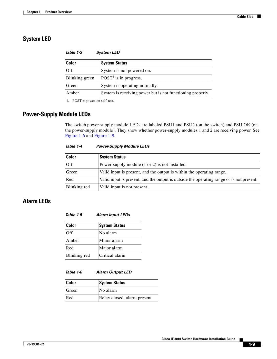
System LED
Table | System LED | |
|
|
|
Color |
| System Status |
|
|
|
Off |
| System is not powered on. |
|
|
|
Blinking green |
| POST1 is in progress. |
Green |
| System is operating normally. |
|
|
|
Amber |
| System is receiving power but is not functioning properly. |
|
|
|
1. POST =
Power-Supply Module LEDs
The switch
Table | ||
|
|
|
Color |
| System Status |
|
|
|
Off |
| |
|
|
|
Green |
| Valid input is present, and the output is within the operating range. |
|
|
|
Red |
| Valid input is present, and the output is outside the operating range or is not present. |
|
|
|
Blinking red |
| Valid input is not present. |
|
|
|
Alarm LEDs
Table | Alarm Input LEDs | ||
|
|
|
|
Color |
| System Status | |
|
|
|
|
Off |
| No alarm | |
|
|
|
|
Amber |
| Minor alarm | |
|
|
|
|
Red |
| Major alarm | |
|
|
|
|
Blinking red |
| Critical alarm | |
|
|
|
|
Table | Alarm Output LED | ||
|
|
| |
Color |
| System Status | |
|
|
| |
Green |
| No alarm | |
|
|
| |
Red |
| Relay closed, alarm present | |
|
|
|
|
Cisco IE 3010 Switch Hardware Installation Guide
|
| ||
|
|