Chapter 1 Product Overview
Cable Side
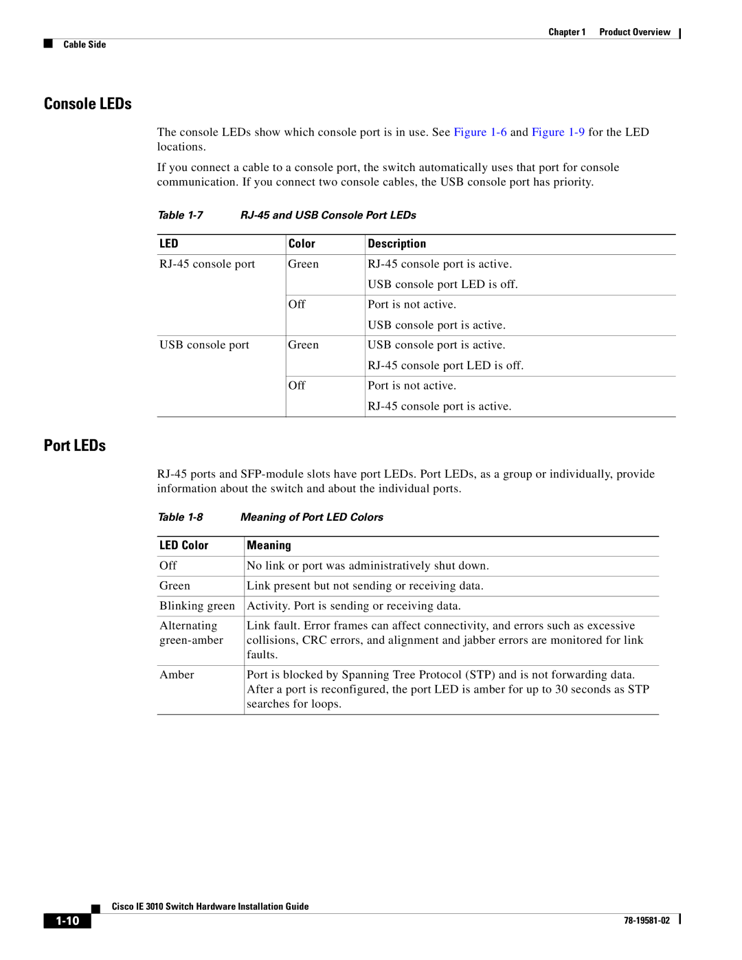
Console LEDs
The console LEDs show which console port is in use. See Figure
If you connect a cable to a console port, the switch automatically uses that port for console communication. If you connect two console cables, the USB console port has priority.
Table | |||
|
|
|
|
LED |
| Color | Description |
|
|
| |
Green | |||
|
|
| USB console port LED is off. |
|
|
|
|
|
| Off | Port is not active. |
|
|
| USB console port is active. |
|
|
| |
USB console port | Green | USB console port is active. | |
|
|
| |
|
|
|
|
|
| Off | Port is not active. |
|
|
| |
|
|
|
|
Port LEDs
Table
LED Color | Meaning |
|
|
Off | No link or port was administratively shut down. |
|
|
Green | Link present but not sending or receiving data. |
|
|
Blinking green | Activity. Port is sending or receiving data. |
|
|
Alternating | Link fault. Error frames can affect connectivity, and errors such as excessive |
collisions, CRC errors, and alignment and jabber errors are monitored for link | |
| faults. |
|
|
Amber | Port is blocked by Spanning Tree Protocol (STP) and is not forwarding data. |
| After a port is reconfigured, the port LED is amber for up to 30 seconds as STP |
| searches for loops. |
|
|
Cisco IE 3010 Switch Hardware Installation Guide
| ||
|