Chapter 3 Power Supply Installation
Figure 3-11 Stripping the Input Power Source Wire
0.25 in. (6.3 mm) ± 0.02 in. (0.5 mm) ![]()
![]()
60531
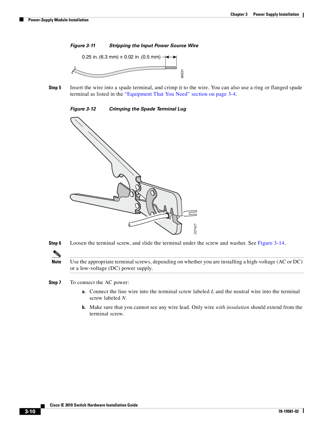
Step 5 Insert the wire into a spade terminal, and crimp it to the wire. You can also use a ring or flanged spade terminal as listed in the “Equipment That You Need” section on page
Figure 3-12 Crimping the Spade Terminal Lug
207427
Step 6 Loosen the terminal screw, and slide the terminal under the screw and washer. See Figure
Note Use the appropriate terminal screws, depending on whether you are installing a
Step 7 To connect the AC power:
a.Connect the line wire into the terminal screw labeled L and the neutral wire into the terminal screw labeled N.
b.Make sure that you cannot see any wire lead. Only wire with insulation should extend from the terminal screw.
Cisco IE 3010 Switch Hardware Installation Guide
| ||
|