Chapter 3 Power Supply Installation
Warning This equipment must be grounded. Never defeat the ground conductor or operate the equipment in the absence of a suitably installed ground conductor. Contact the appropriate electrical inspection authority or an electrician if you are uncertain that suitable grounding is available. Statement 1024
Warning When installing or replacing the unit, the ground connection must always be made first and disconnected last. Statement 1046
Caution Follow the grounding procedure instructions, and use a
Note You can use the grounding lug to attach a wrist strap for ESD protection during servicing.
Follow these steps to install a
Step 1 Use a Phillips screwdriver or a ratcheting torque screwdriver with a Phillips head to remove the ground screw from the cable side of the switch. You need the screw in Step 4.
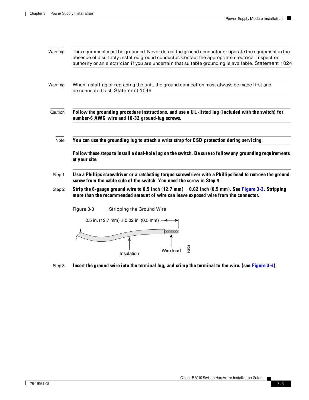
Step 2 Strip the
Figure 3-3 Stripping the Ground Wire
0.5 in. (12.7 mm) ± 0.02 in. (0.5 mm)
Insulation
Wire lead
60528
Step 3 Insert the ground wire into the terminal lug, and crimp the terminal to the wire. (see Figure
Cisco IE 3010 Switch Hardware Installation Guide
|
| ||
|
|