Cisco Systems IE301024TC manual 100-240V~, 50-60Hz, 2A, 10A 10A, Power-Input Terminal

Models: 3010 IE3010 IE301024TC

1 100
Download 100 pages 7.97 Kb
Page 59
Image 59
Power-Input Terminal

Chapter 3 Power Supply Installation
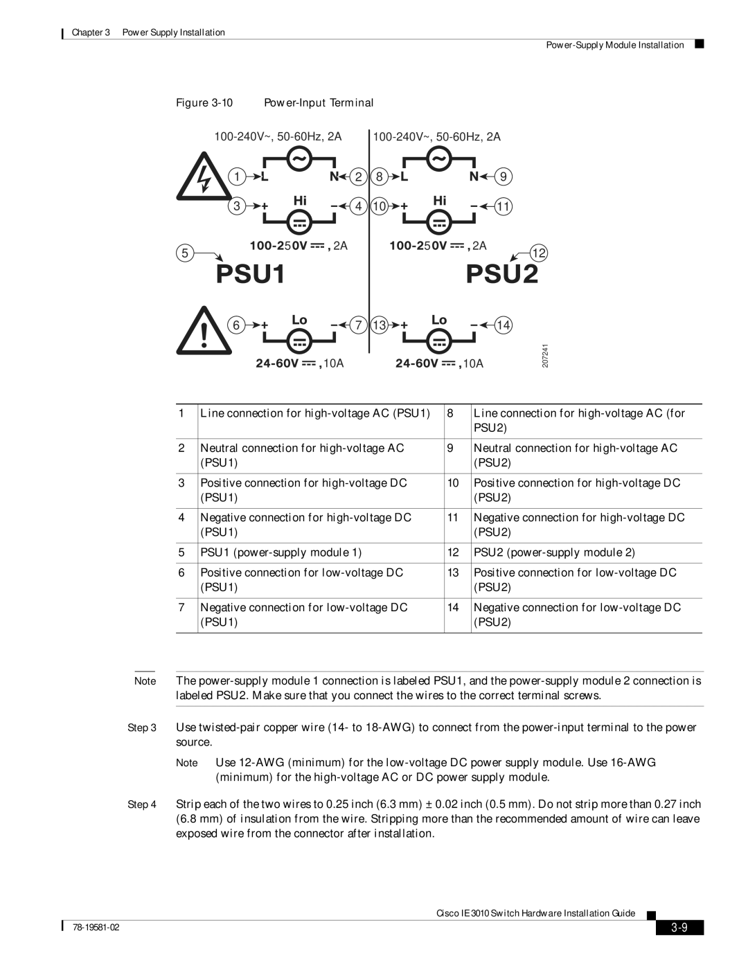
Power-Supply Module Installation

Figure 3-10

Power-Input Terminal


100-240V~, 50-60Hz, 2A

100-240V~, 50-60Hz, 2A


1


2

8

9


3


4

10

11


5

5

2A

5

2A

12


6

7

13

14

100-240V~, 50-60Hz, 2A10A 10AManual backgroundManual backgroundManual backgroundManual backgroundManual background10A Manual backgroundManual backgroundManual backgroundManual backgroundManual background10A

207241

1

Line connection for high-voltage AC (PSU1)

8

Line connection for high-voltage AC (for


PSU2)


2

Neutral connection for high-voltage AC

9

Neutral connection for high-voltage AC


(PSU1)


(PSU2)


3

Positive connection for high-voltage DC

10

Positive connection for high-voltage DC


(PSU1)


(PSU2)


4

Negative connection for high-voltage DC

11

Negative connection for high-voltage DC


(PSU1)


(PSU2)


5

PSU1 (power-supply module 1)

12

PSU2 (power-supply module 2)


6

Positive connection for low-voltage DC

13

Positive connection for low-voltage DC


(PSU1)


(PSU2)


7

Negative connection for low-voltage DC

14

Negative connection for low-voltage DC


(PSU1)


(PSU2)


Note The power-supply module 1 connection is labeled PSU1, and the power-supply module 2 connection is labeled PSU2. Make sure that you connect the wires to the correct terminal screws.

Step 3 Use twisted-pair copper wire (14- to 18-AWG) to connect from the power-input terminal to the power source.

Note Use 12-AWG (minimum) for the low-voltage DC power supply module. Use 16-AWG (minimum) for the high-voltage AC or DC power supply module.

Step 4 Strip each of the two wires to 0.25 inch (6.3 mm) ± 0.02 inch (0.5 mm). Do not strip more than 0.27 inch (6.8 mm) of insulation from the wire. Stripping more than the recommended amount of wire can leave exposed wire from the connector after installation.

Cisco IE 3010 Switch Hardware Installation Guide


78-19581-02

3-9


Page 59
Image 59
Cisco Systems IE301024TC manual 100-240V~, 50-60Hz, 2A, 10A 10A, Power-Input Terminal