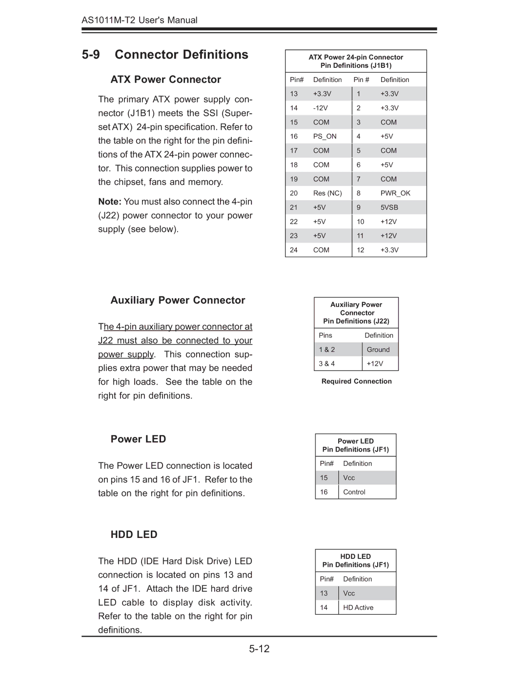
5-9 Connector Definitions
ATX Power Connector
The primary ATX power supply con- nector (J1B1) meets the SSI (Super- set ATX)
Note: You must also connect the
Auxiliary Power Connector
The
Power LED
The Power LED connection is located on pins 15 and 16 of JF1. Refer to the table on the right for pin defi nitions.
ATX Power
Pin Definitions (J1B1)
Pin# | Defi nition | Pin # | Defi nition | |
13 | +3.3V | 1 | +3.3V | |
14 |
| +3.3V | ||
2 | ||||
15 | COM |
| COM | |
3 | ||||
16 | PS_ON |
| +5V | |
4 | ||||
17 | COM |
| COM | |
5 | ||||
18 | COM |
| +5V | |
6 | ||||
19 | COM |
| COM | |
7 | ||||
20 | Res (NC) |
| PWR_OK | |
8 | ||||
21 | +5V |
| 5VSB | |
9 | ||||
22 | +5V | 10 | +12V | |
23 | +5V | 11 | +12V | |
24 | COM | 12 | +3.3V | |
|
|
|
|
Auxiliary Power
Connector
Pin Definitions (J22)
Pins | Defi nition | |
1 & 2 | Ground | |
3 & 4 | +12V | |
|
|
Required Connection
Power LED
Pin Definitions (JF1)
Pin# Defi nition
15Vcc
16Control
HDD LED
The HDD (IDE Hard Disk Drive) LED connection is located on pins 13 and 14 of JF1. Attach the IDE hard drive LED cable to display disk activity. Refer to the table on the right for pin defi nitions.
HDD LED
Pin Definitions (JF1)
Pin# Defi nition
13Vcc
14HD Active