Chapter 5: Advanced Motherboard Setup
5-12 Floppy, IDE, Parallel Port and SATA Drive Connections
Use the following information to connect the fl oppy and hard disk drive cables.
The fl oppy disk drive cable has seven twisted wires.
A red mark on a wire typically designates the location of pin 1.
A single fl oppy disk drive ribbon cable has 34 wires and two connectors to provide for two fl oppy disk drives. The connector with twisted wires always connects to drive A, and the connector that does not have twisted wires always connects to drive B.
The
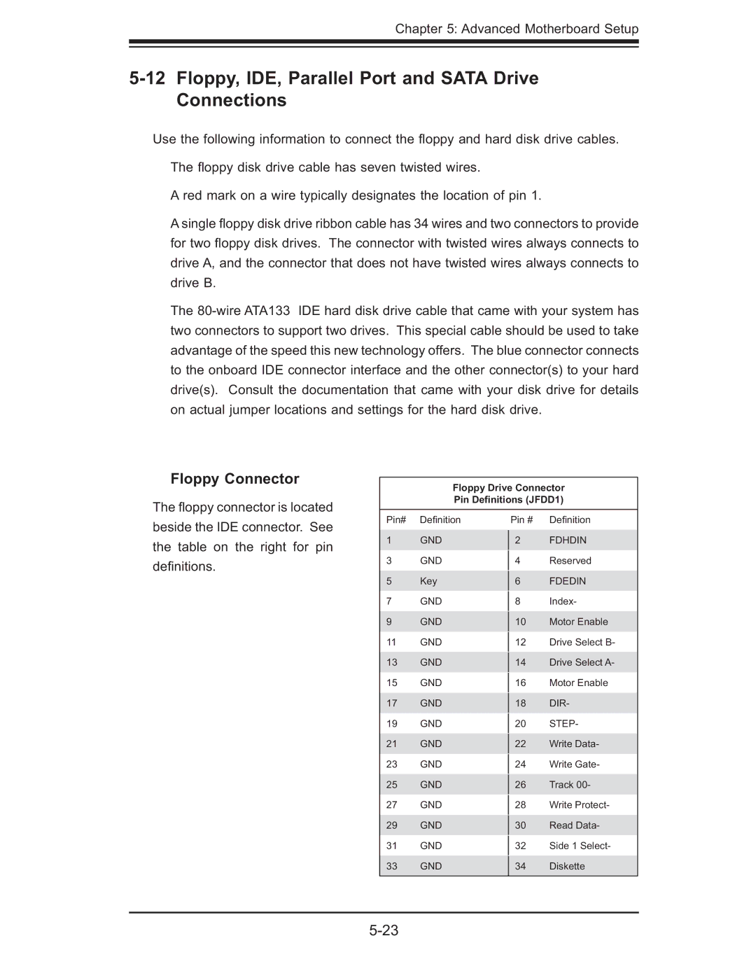
Floppy Connector
The fl oppy connector is located
Floppy Drive Connector Pin Definitions (JFDD1)
beside the IDE connector. See the table on the right for pin defi nitions.
Pin# Defi nition
1GND
3GND
5Key
7GND
9GND
11 GND
13 GND
15 GND
17 GND
19GND
21GND
23GND
25GND
27GND
29GND
31GND
33GND
Pin # Defi nition
2FDHDIN
4Reserved
6FDEDIN
8Index-
10Motor Enable
12Drive Select B-
14Drive Select A-
16Motor Enable
18 DIR-
20 STEP-
22Write Data-
24Write Gate-
26Track 00-
28Write Protect-
30Read Data-
32Side 1 Select-
34Diskette