SBI-7127R-S6 Blade Module User’s Manual
4-1 Control Panel
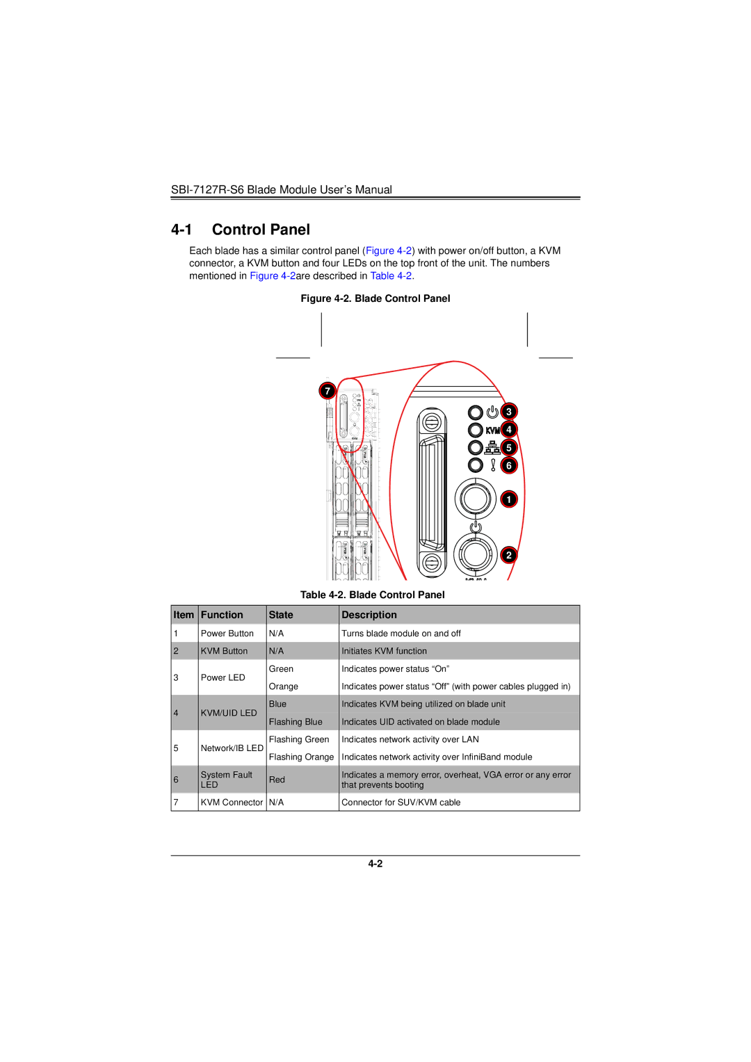
Each blade has a similar control panel (Figure
Figure 4-2. Blade Control Panel
![]() 7
7 ![]()
![]()
![]()
![]()
![]()
![]()
![]()
![]()
![]() 3
3
![]()
![]()
![]()
![]()
![]()
![]()
![]()
![]()
![]()
![]()
![]() 4
4
![]()
![]()
![]()
![]()
![]() 5
5 ![]()
![]()
![]()
![]()
![]() 6
6
![]() 1
1
![]() 2
2
|
| Table | ||
|
|
|
| |
Item | Function | State | Description | |
1 | Power Button | N/A | Turns blade module on and off | |
|
|
|
| |
2 | KVM Button | N/A | Initiates KVM function | |
3 | Power LED | Green | Indicates power status “On” | |
Orange | Indicates power status “Off” (with power cables plugged in) | |||
|
| |||
|
|
|
| |
4 | KVM/UID LED | Blue | Indicates KVM being utilized on blade unit | |
Flashing Blue | Indicates UID activated on blade module | |||
|
| |||
5 | Network/IB LED | Flashing Green | Indicates network activity over LAN | |
Flashing Orange | Indicates network activity over InfiniBand module | |||
|
| |||
|
|
|
| |
6 | System Fault | Red | Indicates a memory error, overheat, VGA error or any error | |
LED | that prevents booting | |||
|
| |||
7 | KVM Connector | N/A | Connector for SUV/KVM cable | |
|
|
|
| |