Chapter 4: Blade Module Features
Power Button
Each blade has its own power button so that individual blade units within the enclosure may be turned on or off independently of the others. Press the power button (#1) to turn on the blade server. The power LED (#3) will turn green. To turn off, press and hold the power button for >4 seconds and the power LED will turn orange.
KVM Button
KVM stands for Keyboard/Video/Mouse. With KVM, a user can control multiple blades with a single keyboard/video/mouse setup. Connect your keyboard, mouse and monitor to the USB and VGA connectors on the CMM module, then push the KVM button on the control panel of the blade module you wish to access.
LED Indicators
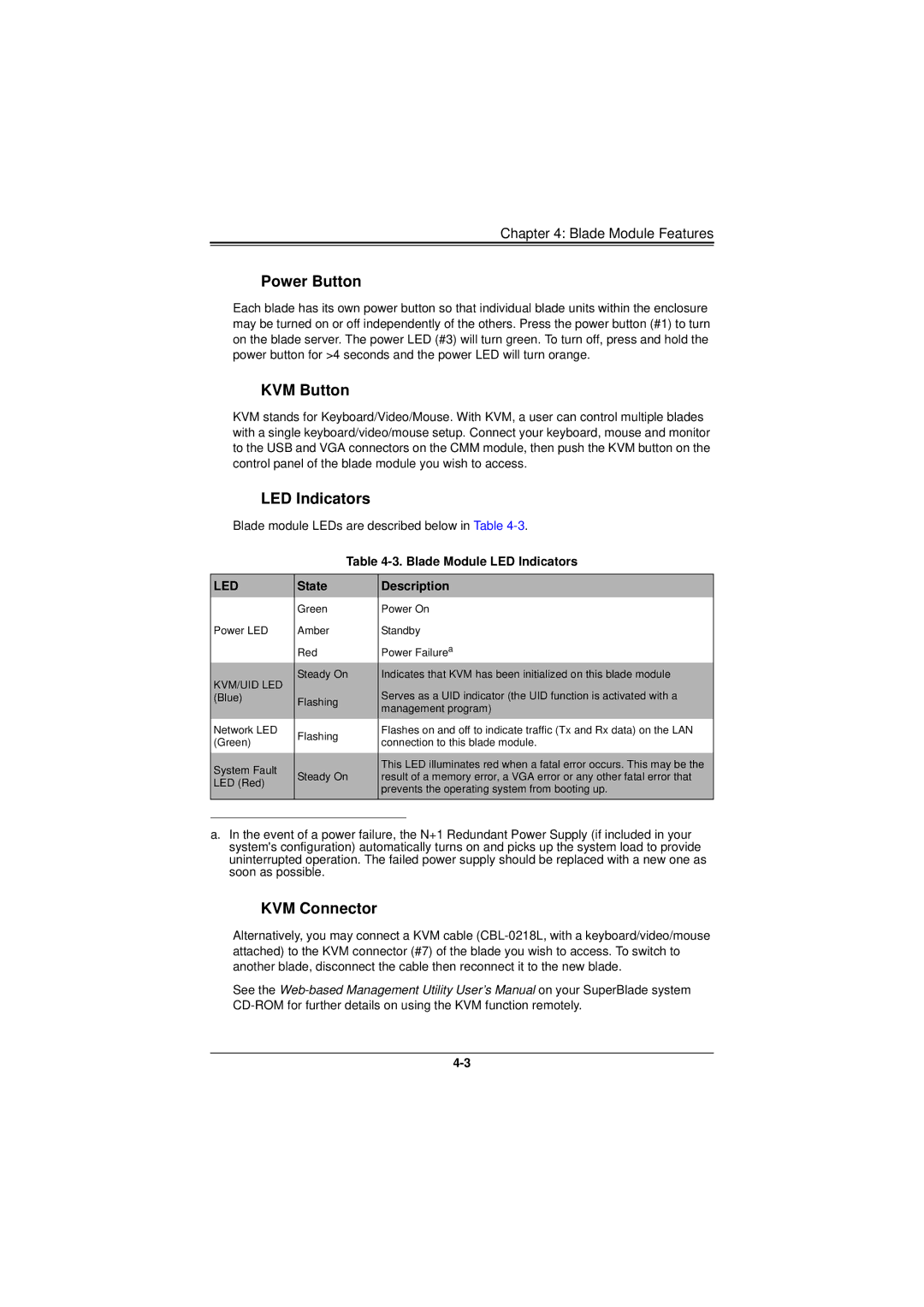
Blade module LEDs are described below in Table
Table
LED | State | Description | |
| Green | Power On | |
Power LED | Amber | Standby | |
| Red | Power Failurea | |
KVM/UID LED | Steady On | Indicates that KVM has been initialized on this blade module | |
| Serves as a UID indicator (the UID function is activated with a | ||
(Blue) | Flashing | ||
| management program) | ||
|
| ||
Network LED | Flashing | Flashes on and off to indicate traffic (Tx and Rx data) on the LAN | |
(Green) | connection to this blade module. | ||
| |||
|
|
| |
System Fault | Steady On | This LED illuminates red when a fatal error occurs. This may be the | |
result of a memory error, a VGA error or any other fatal error that | |||
LED (Red) | |||
| prevents the operating system from booting up. | ||
|
| ||
|
|
|
a.In the event of a power failure, the N+1 Redundant Power Supply (if included in your system's configuration) automatically turns on and picks up the system load to provide uninterrupted operation. The failed power supply should be replaced with a new one as soon as possible.
KVM Connector
Alternatively, you may connect a KVM cable
See the
