SC827 Chassis Manual
| FAN4 |
|
| + | BAR CODE |
| 33 |
|
| + 1 | #D2 OH |
32 |
| |
| ||
| (FAN) | |
| + | #D1 |
31 |
| |
|
| |
| 1 | #D0 |
FAN3
To P/S | FAN2 |
|
|
|
| HB |
| 27 |
|
| SAS827T |
|
|
|
|
| |
| 30REV 1.01 |
|
|
|
|
| |
+ | 1 | #C2 |
|
| + | 1 | #B2 |
+ |
| JP30: |
|
| + |
|
|
|
|
|
|
|
| ||
| 29 |
|
|
| 26 |
| |
|
|
|
| ||||
|
|
|
| (FAN) | |||
+ | 1 | #C1 | (FAN) |
| + | 1 | #B1 |
|
|
|
|
|
| ||
| 28 |
|
|
| 25 | (PWR) | |
| 1 |
|
|
| 1 |
| |
|
|
|
| (PWR) |
| ||
|
|
| DESIGNED IN USA |
|
| ||
| #C0 |
|
|
| #B0 |
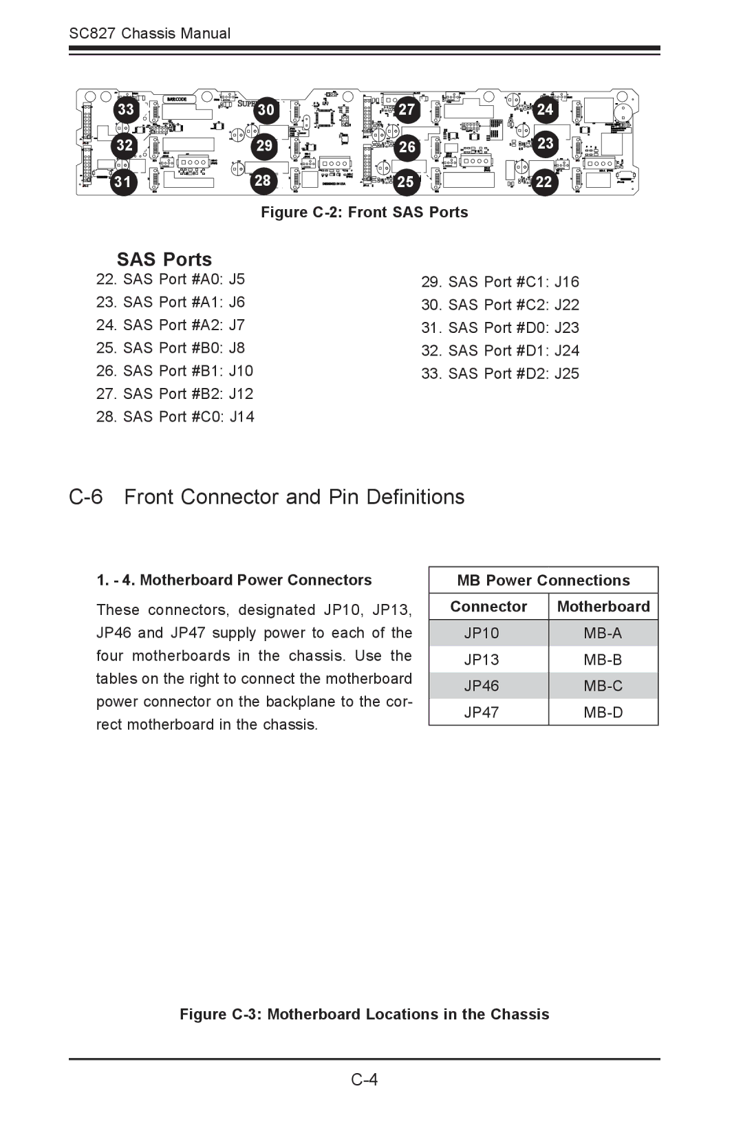
Figure C-2: Front SAS Ports
+ | 24 | FAN1 |
|
| |
| 1 | #A2 |
| + |
|
| 1 |
|
| 23 |
|
| + | #A1 |
|
| |
| 22 (FAN) | #A0 |
+
BUZZER RESET
SAS Ports
22. | SAS Port #A0: J5 | 29. SAS Port #C1: J16 | |
23. | SAS Port #A1: J6 | 30. SAS Port #C2: J22 | |
24. | SAS Port #A2: J7 | 31. SAS Port #D0: J23 | |
25. | SAS Port #B0: | J8 | 32. SAS Port #D1: J24 |
26. | SAS Port #B1: | J10 | 33. SAS Port #D2: J25 |
27.SAS Port #B2: J12
28.SAS Port #C0: J14
C-6 Front Connector and Pin Definitions
1. - 4. Motherboard Power Connectors
These connectors, designated JP10, JP13, JP46 and JP47 supply power to each of the four motherboards in the chassis. Use the tables on the right to connect the motherboard power connector on the backplane to the cor- rect motherboard in the chassis.
MB Power Connections
Connector | Motherboard |
JP10 | |
JP13 | |
JP46 | |
JP47 | |
|
|