SC827 Chassis Manual
1. - 3. Motherboard Power Connectors
These connectors, designated JPW1, JPW2, and JPW3 supply power the four motherboard nodes in the chassis.
4. - 7. Chassis Fan Connectors
These connectors, designated JP54, JP55, JP56 and JP57 supply power to the chassis. cooling fans.
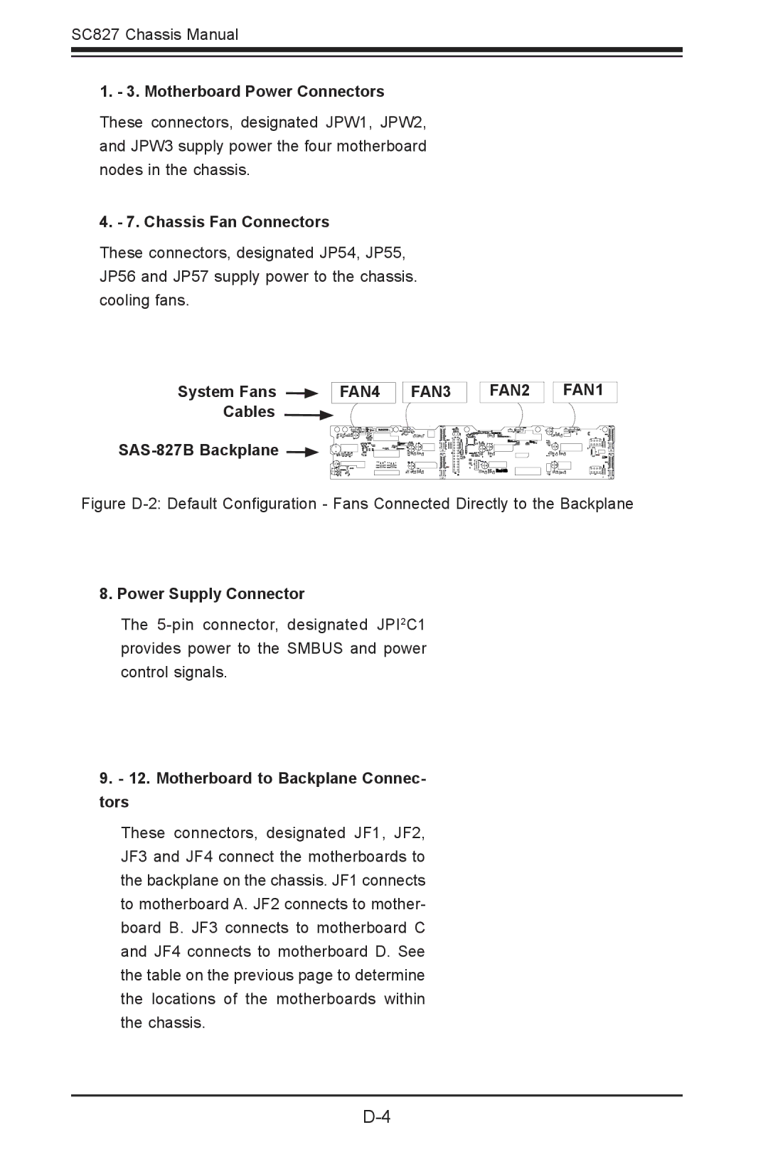
System Fans | FAN4 |
| FAN3 |
Cables
BAR CODE
SAS-827B Backplane 
FAN2
SAS827B
FAN1
Figure D-2: Default Configuration - Fans Connected Directly to the Backplane
8. Power Supply Connector
The
9.- 12. Motherboard to Backplane Connec- tors
These connectors, designated JF1, JF2, JF3 and JF4 connect the motherboards to the backplane on the chassis. JF1 connects to motherboard A. JF2 connects to mother- board B. JF3 connects to motherboard C and JF4 connects to motherboard D. See the table on the previous page to determine the locations of the motherboards within the chassis.