Appendix C:
Connector, Jumper and Pin Definitions
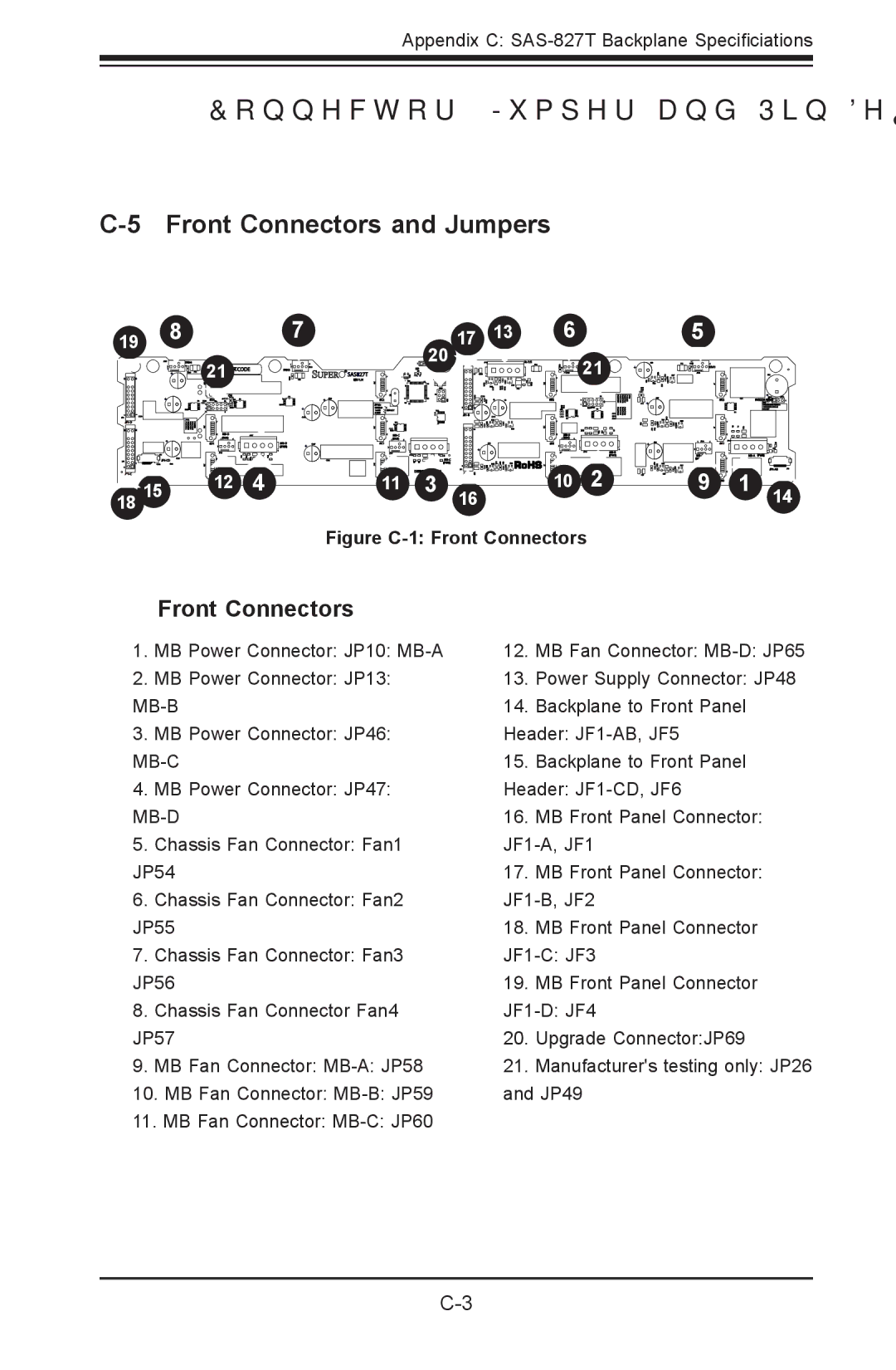
C-5 Front Connectors and Jumpers
191 18
17
201 171 131
16
15
FAN4
+
+ |
+
![]()
![]()
![]()
181 151
211 BAR CODE
![]() OH #D2
OH #D2 ![]()
![]()
![]()
#D1
#D0121 14
FAN3
![]()
![]()
![]() SAS827T
SAS827T
REV 1.01
| + | #C2 |
| + | JP30: |
|
| |
|
| |
|
| (FAN) |
+ | #C1 | |
(PWR) | 1 | |
|
| |
|
| #C011 |
HB
+
+
+![]()
DESIGNED1IN USA ![]()
3
161
To P/S
![]()
![]()
![]()
![]()
![]()
![]()
![]() FAN2211
FAN2211
#B2
![]() (FAN)
(FAN)
#B1
#B0101 12
+ | FAN1 |
| + |
| + |
| |
| (FAN) |
![]()
![]()
![]()
![]()
![]()
![]()
![]()
![]()
![]()
![]()
![]()
![]() 19
19
|
| + |
#A2 |
| BUZZER RESET |
#A1 |
|
|
| ||
#A0 | 1 | |
|
| 1 |
Figure C-1: Front Connectors
Front Connectors
1.MB Power Connector: JP10:
2.MB Power Connector: JP13:
MB-B
3.MB Power Connector: JP46:
4.MB Power Connector: JP47:
5.Chassis Fan Connector: Fan1 JP54
6.Chassis Fan Connector: Fan2 JP55
7.Chassis Fan Connector: Fan3 JP56
8.Chassis Fan Connector Fan4 JP57
9.MB Fan Connector:
10.MB Fan Connector:
11.MB Fan Connector:
12.MB Fan Connector:
13.Power Supply Connector: JP48
14.Backplane to Front Panel Header:
15.Backplane to Front Panel Header:
16.MB Front Panel Connector:
JF1-A, JF1
17.MB Front Panel Connector:
18.MB Front Panel Connector
19.MB Front Panel Connector
20.Upgrade Connector:JP69
21.Manufacturer's testing only: JP26 and JP49