SC827 Chassis Manual
C-7 Front Jumper Locations and Pin Definitions
JP30
FAN4 |
| To P/S | FAN2 |
BAR CODE | FAN3 | HB |
|
+ |
| SAS827T |
|
|
| REV 1.01 |
|
+ |
| OH |
|
| + |
|
#D2 |
| + | #C2 | #B2 | ||
|
| + |
| JP30: | + |
|
|
|
|
|
| ||
|
|
|
|
|
| |
|
|
|
|
|
| |
|
|
|
| |||
+ |
| (FAN) |
| (FAN) |
| (FAN) |
#D1 | + | #C1 |
| #B1 | ||
|
| (PWR) |
| + |
| |
|
|
|
|
|
|
|
| ||
|
|
| (PWR) |
| DESIGNED IN USA | ||
|
| ||
#D0 | #C0 |
| #B0 |
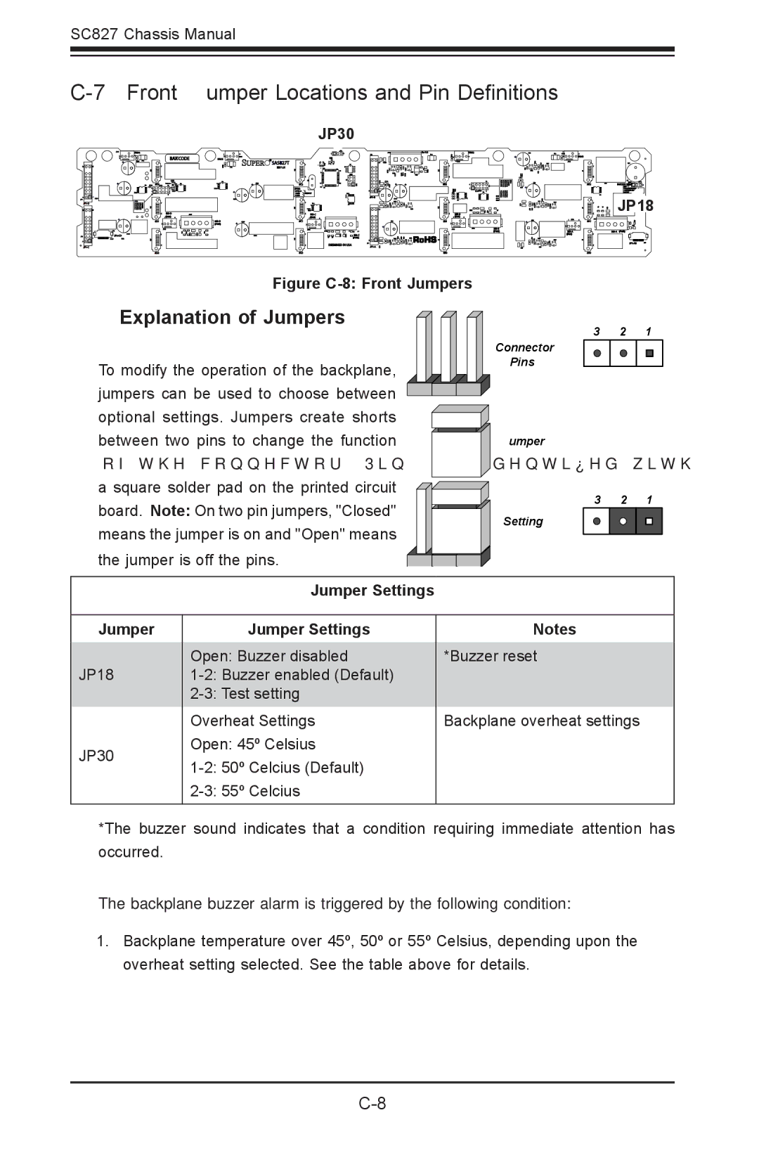
Figure C-8: Front Jumpers
Explanation of Jumpers
To modify the operation of the backplane, jumpers can be used to choose between optional settings. Jumpers create shorts between two pins to change the function of the connector. Pin 1 is identified with a square solder pad on the printed circuit board. Note: On two pin jumpers, "Closed" means the jumper is on and "Open" means
the jumper is off the pins.
Jumper Settings
+ | FAN1 |
| + |
#A2 | BUZZER RESET |
![]()
![]() +
+
![]()
![]()
![]()
![]()
![]()
![]() JP18
JP18
+ |
| #A1 |
|
| |
(PWR) | ||
| (FAN) |
|
|
| |
|
| #A0 |
3 2 1
Connector
Pins
Jumper
3 2 1
Setting
Jumper
JP18
JP30
Jumper Settings
Open: Buzzer disabled
Notes
*Buzzer reset
Backplane overheat settings
*The buzzer sound indicates that a condition requiring immediate attention has occurred.
The backplane buzzer alarm is triggered by the following condition:
1.Backplane temperature over 45º, 50º or 55º Celsius, depending upon the overheat setting selected. See the table above for details.