SC827 Chassis Manual |
|
|
|
|
|
|
| |||||
|
|
| ||||||||||
|
|
| JP30 |
|
|
| JP69 |
|
|
|
| |
| + | FAN4 |
| FAN3 |
|
| SPI |
| FAN2 |
|
| |
Buzzer |
|
| BAR CODE |
|
|
|
|
| + | FAN1 | ||
|
|
|
|
|
|
|
| SAS827B |
| |||
|
|
|
|
|
|
|
|
|
| REV 1.01 |
| |
|
|
|
|
|
|
|
|
|
| DESIGNED IN USA |
|
|
+ |
|
|
|
|
| + |
|
|
| + | + |
|
|
|
|
|
|
|
|
|
|
|
|
| |
|
|
|
|
|
| + |
|
| + |
|
|
|
|
|
|
|
| BUZZER RESET |
|
|
|
| JP36JP35 |
|
|
+ |
|
|
| JP18 | + |
| DEBUG | TO PS | + | |||
|
|
|
|
|
|
|
| J21 |
|
|
| |
+ |
|
|
|
|
|
| + |
|
|
| ||
|
|
|
|
|
|
|
|
|
|
|
| |
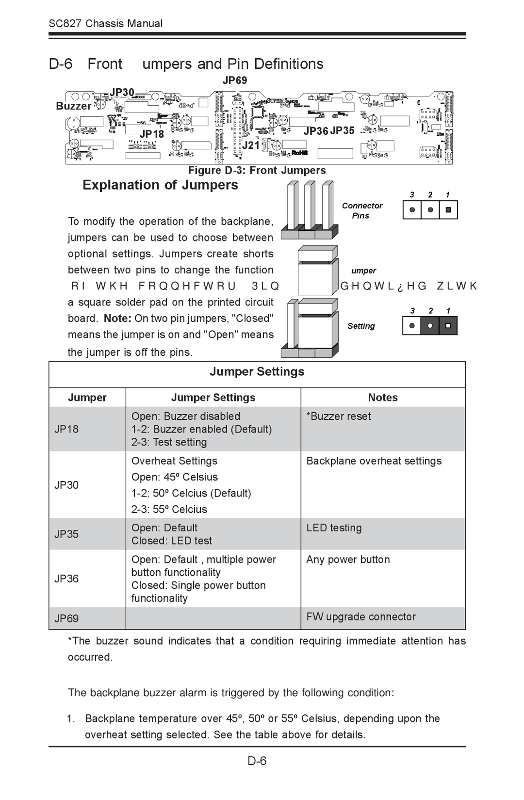
Figure D-3: Front Jumpers
Explanation of Jumpers | 3 | 2 | 1 | |
| ||||
| Connector |
|
| |
To modify the operation of the backplane, | Pins |
|
| |
|
|
| ||
jumpers can be used to choose between |
|
|
| |
optional settings. Jumpers create shorts |
|
|
| |
between two pins to change the function | Jumper |
|
| |
of the connector. Pin 1 is identified with |
|
|
| |
a square solder pad on the printed circuit | 3 | 2 | 1 | |
board. Note: On two pin jumpers, "Closed" | ||||
Setting |
|
| ||
means the jumper is on and "Open" means |
|
| ||
|
|
|
the jumper is off the pins.
Jumper Settings
Jumper
JP18
JP30
JP35
JP36
JP69
Jumper Settings
Open: Buzzer disabled
Open: Default
Closed: LED test
Open: Default , multiple power button functionality
Closed: Single power button functionality
Notes
*Buzzer reset
Backplane overheat settings
LED testing
Any power button
FW upgrade connector
*The buzzer sound indicates that a condition requiring immediate attention has occurred.
The backplane buzzer alarm is triggered by the following condition:
1.Backplane temperature over 45º, 50º or 55º Celsius, depending upon the overheat setting selected. See the table above for details.
