![]()
![]()
![]()
![]()
![]()
![]()
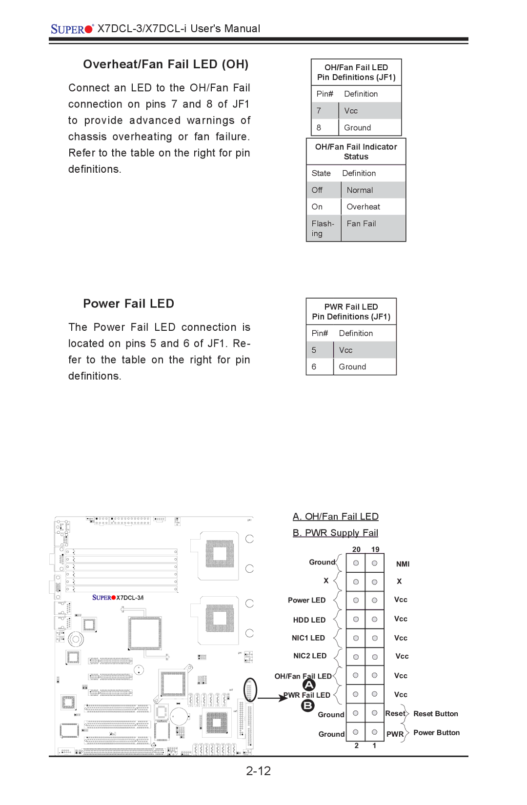
Overheat/Fan Fail LED (OH)
Connect an LED to the OH/Fan Fail connection on pins 7 and 8 of JF1 to provide advanced warnings of chassis overheating or fan failure. Refer to the table on the right for pin definitions.
OH/Fan Fail LED
Pin Definitions (JF1)
Pin# Definition
7Vcc
8Ground
OH/Fan Fail Indicator
Status
State Definition
Off | Normal | |
On | Overheat | |
Flash- | Fan Fail | |
ing |
| |
|
|
Power Fail LED
The Power Fail LED connection is located on pins 5 and 6 of JF1. Re- fer to the table on the right for pin definitions.
PWR Fail LED
Pin Definitions (JF1)
Pin# Definition
5Vcc
6Ground
A. OH/Fan Fail LED B. PWR Supply Fail
![]()
![]()
![]()
![]()
![]()
Ground![]()
X
Power LED
HDD LED
NIC1 LED
NIC2 LED
OH/Fan Fail LED
A
PWR Fail LED
B
Ground
Ground
20 | 19 |
| NMI |
| X |
| Vcc |
| Vcc |
| Vcc |
| Vcc |
| Vcc |
| Vcc |
| Reset |
| PWR |
2 | 1 |
Reset Button
Power Button