Chapter 3: Installation
HDD/FP UID Switch
The HDD/UID Switch connections are located on pins 13/14 of JF1. Attach a
NIC1 LED Indicator
The NIC (Network Interface Controller) LED connections for GLAN port 1 are located on pins 11 and 12 of JF1. Attach a NIC LED cable to display LAN Port1 connections and activities. Refer to the table on the right for pin definitions.
HDD/UID Switch
Pin Definitions (JF1)
Pin# Definition
13UID Signal/3.3V SB
14HDD Active
GLAN1 LED
Pin Definitions (JF1)
Pin# Definition
11NIC1 Activity
12NIC1 Link
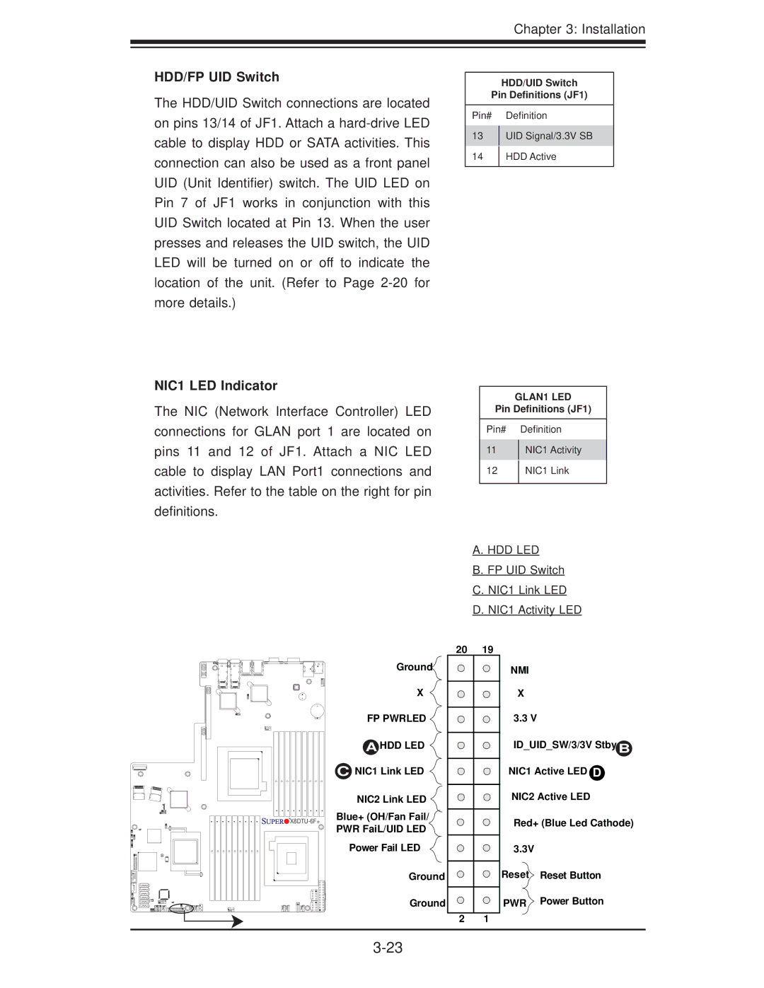
A.HDD LED
B.FP UID Switch
C.NIC1 Link LED
D.NIC1 Activity LED
![]()
![]()
![]()
![]()
![]()
![]() X8DTU-6F+
X8DTU-6F+
Ground
X
FP PWRLED ![]()
A HDD LED
CNIC1 Link LED ![]()
NIC2 Link LED
Blue+ (OH/Fan Fail/
PWR FaiL/UID LED
Power Fail LED
Ground
Ground
20 | 19 |
2 1
NMI
X
3.3 V
ID_UID_SW/3/3V Stby B
NIC1 Active LED D
NIC2 Active LED
Red+ (Blue Led Cathode)
3.3V
Reset Reset Button
PWR Power Button