![]()
![]()
![]()
![]() X8DTU-6F+/X8DTU-6TF+/X8DTU-6(T)F+-LR
X8DTU-6F+/X8DTU-6TF+/X8DTU-6(T)F+-LR
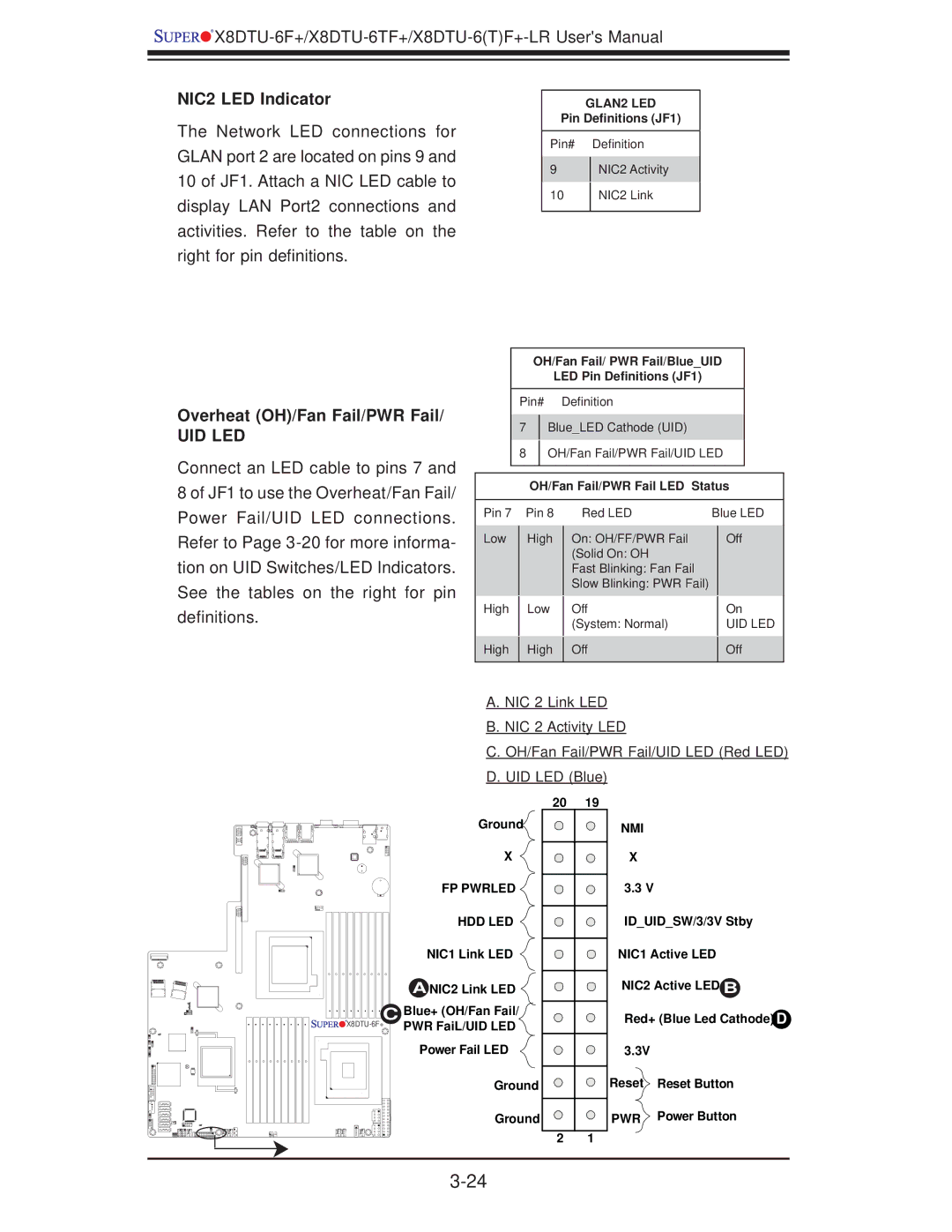
NIC2 LED Indicator
The Network LED connections for GLAN port 2 are located on pins 9 and 10 of JF1. Attach a NIC LED cable to display LAN Port2 connections and activities. Refer to the table on the right for pin definitions.
Overheat (OH)/Fan Fail/PWR Fail/
UID LED
Connect an LED cable to pins 7 and 8 of JF1 to use the Overheat/Fan Fail/ Power Fail/UID LED connections. Refer to Page
GLAN2 LED
Pin Definitions (JF1)
Pin# Definition
9NIC2 Activity
10NIC2 Link
OH/Fan Fail/ PWR Fail/Blue_UID
LED Pin Definitions (JF1)
Pin# Definition
7Blue_LED Cathode (UID)
8OH/Fan Fail/PWR Fail/UID LED
OH/Fan Fail/PWR Fail LED Status
Pin 7 |
| Pin 8 |
| Red LED | Blue LED | |
Low |
| High |
| On: OH/FF/PWR Fail |
| Off |
|
|
| ||||
|
|
|
| (Solid On: OH |
|
|
|
|
|
| Fast Blinking: Fan Fail |
|
|
|
|
|
| Slow Blinking: PWR Fail) |
|
|
High |
| Low |
| Off |
| On |
|
|
| ||||
|
|
|
| (System: Normal) |
| UID LED |
High |
| High |
| Off |
| Off |
|
|
| ||||
|
|
|
|
|
|
|
A. NIC 2 Link LED B. NIC 2 Activity LED
C. OH/Fan Fail/PWR Fail/UID LED (Red LED) D. UID LED (Blue)
| Ground |
| X |
| FP PWRLED |
| HDD LED |
| NIC1 Link LED |
| A NIC2 Link LED |
C Blue+ (OH/Fan Fail/ | |
PWR FaiL/UID LED | |
| |
| Power Fail LED |
| Ground |
| Ground |
20 19
2 1
NMI
X
3.3 V
ID_UID_SW/3/3V Stby
NIC1 Active LED
NIC2 Active LED B
Red+ (Blue Led Cathode) D
3.3V
Reset Reset Button
PWR Power Button