Chapter 3: Installation
3-6 Connecting Cables
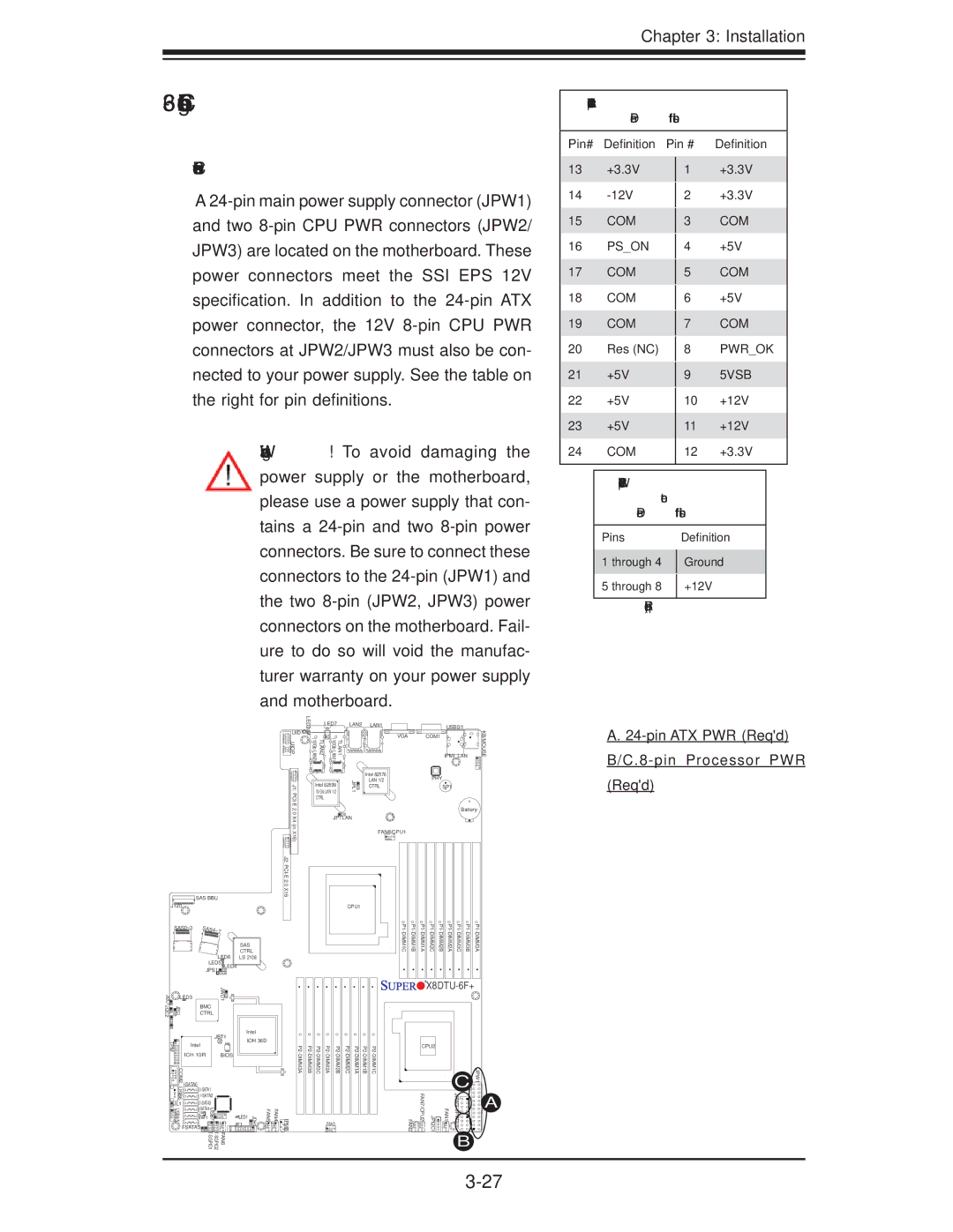
Power Connectors
A
Warning! To avoid damaging the power supply or the motherboard, please use a power supply that con- tains a
LED2 | LED7 | LAN2 LAN1 |
| USB0/1 | KB/MOUSE | |
UID | TLAN2 (10GbLAN2) | (10GbLAN1) | TLAN1 | COM1 |
| |
UIOP |
| |||||
|
|
| VGA |
|
| |
|
|
|
|
| IPMI_LAN |
|
ATX Power
Pin Definitions
Pin# | Definition | Pin # | Definition | |
13 | +3.3V |
| +3.3V | |
| 1 | |||
14 |
|
| +3.3V | |
| 2 | |||
15 | COM |
|
| COM |
| 3 | |||
16 | PS_ON |
|
| +5V |
| 4 | |||
17 | COM |
|
| COM |
| 5 | |||
18 | COM |
|
| +5V |
| 6 | |||
19 | COM |
|
| COM |
| 7 | |||
20 | Res (NC) |
|
| PWR_OK |
| 8 | |||
21 | +5V |
|
| 5VSB |
| 9 | |||
22 | +5V |
|
| +12V |
| 10 | |||
23 | +5V |
| 11 | +12V |
24 | COM |
| 12 | +3.3V |
|
|
|
|
|
12V
nector
Pin Definitions
Pins |
| Definition |
1 through 4 |
| Ground |
| ||
5 through 8 |
| +12V |
| ||
|
|
|
(Required)
A. |
|
SAS BBU
J120![]()
![]()
![]()
![]()
![]()
![]()
![]()
![]()
![]()
![]()
![]()
![]()
![]()
![]()
![]()
![]()
![]()
![]()
![]()
![]()
![]()
![]()
![]()
![]()
![]()
![]()
SAS0~3
SAS
CTRL
LED6 LSI 2108
LED5![]() LED4
LED4
JPS1 ![]()
![]()
J2:
J1:
Intel 82599 | JPL1 |
10 Gb LAN 1/2 |
|
CTRL |
|
JPTLAN |
|
CPU1
Intel 82576
LAN 1/2
CTRL
FAN8/CPU1
PHY
SP1
Battery
(Req'd) |
JI2C1 | LED3 | JWD1 |
|
| |
JI2C2 | JPG1 | BMC |
CTRL |


 X8DTU-6F+
TPM | JBT1 | |
Intel |
| |
|
| |
| ICH 10R | BIOS |
COM2 |
|
|
| ||
USB6 |
| |
|
| |
JL1 |
| |
USB4/5 |
| |
JWF1 USB7 |
| |
| ||
| FAN6 | |
Intel
IOH 36D
JF1 | JOH1 | FAN5 |
LED1 |
|
|
FAN4 | IPMB |
CPU2 |
|
|
| ||||||||||
|
|
| C | JPW1 | |||||||||
|
|
|
|
|
|
|
|
|
|
|
|
| |
|
|
| FAN3 |
|
|
|
| FAN2 | FAN7/CPU2 | JPI2C1 | FAN1 | JPW3 JPW2 |
|
|
|
|
|
|
|
|
|
|
|
|
|
| |
|
|
|
|
|
|
|
|
|
|
|
| B |
|
![]()
![]() A
A