TANDBERG GW | Data port Command Interface User Guide |
2.Connecting to the Data port Command Interface through the
The
2.1.Hardware and Cabling
The pin outs for the
Pin no | Signal | Description | Direction |
1 | CD | Carrier detect | To DTE |
2 | RD | Receive data | To DTE |
3 | TD | Transmit data | From DTE |
4 | DTR | Data terminal ready | From DTE |
5 |
| Ground |
|
6 | DSR | Data set ready | To DTE |
7 | RTS | Ready to send | From DTE |
8 | CTS | Clear to send | To DTE |
9 | RI | Ring indicator | To DTE |
NOTE! A straight through cable should be used between the TANDBERG GW’s
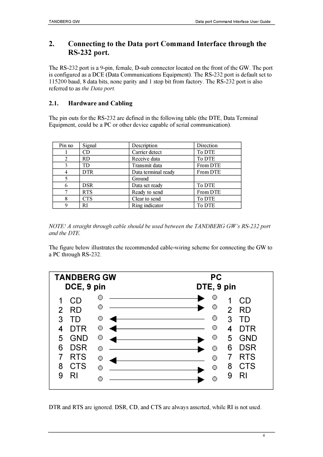
The figure below illustrates the recommended cable-wiring scheme for connecting the GW to a PC through RS-232.
TANDBERG GW | PC |
| |
| DCE, 9 pin | DTE, 9 pin |
|
1 | CD | 1 | CD |
2 | RD | 2 | RD |
3 | TD | 3 | TD |
4 | DTR | 4 | DTR |
5 | GND | 5 | GND |
6 | DSR | 6 | DSR |
7 | RTS | 7 | RTS |
8 | CTS | 8 | CTS |
9 | RI | 9 | RI |
|
|
|
|
DTR and RTS are ignored. DSR, CD, and CTS are always asserted, while RI is not used.
4