Power Module
First Printing JA N
Serial
Revised OCT
ST Rument S ER IA L Number S
Μι τεπιΙδ1ι~ τ±#,I R Uτ1 15 491-Τ ti T3tA
EK T R O N IX, ΤΕΚ , SCO PE-M O B I LE
Chapitre 2 Inst RU Ctio NS D Utilisatio N
Vii
Sect i on 1 Specificatio N
Operati NG I Nstructions
Contents
System Des i gn Directions
Illustrations
Parts
Change I Nformation
211
Unsolder these wires to remove
Dc power supply board Α11
Dime sio
REV JAN
Α10 Comp onent R eferen ce Chart
Do Not Operate Wit hout Covers
Terms 1η This Manual
Terms As Marked on Equipment
Ervice Safety Summary
Ise ά la masse de Ι appareil
Te rm es utilisέs da ns ce manuel
Re ρdres gravά s ωι Ι a pp areil
So urce dalime ntatio n
Source dali mentation
Ne d6pannez pas se υl
Netzs pannungsversorgung
Diese m Handbuch
Markίerungen auf dem Gedit
Sc hutzerdungskonta kt
1983
Sicherheitsangaben FUR DEN Service
~F ι ο
TiΟ ib 3 1J10- Miff.-c,-4
Vrms
ΜΡυ J 3Υ η eΧι t α c Lb C45 h -1t ο
~ ι ι ~~ Ζι ~3 θ ι
S3A~0 a
295ϋ00 TM 5006 Power Modu le ADD JAN
Pard
Electrical Characteristics
Supplies
Seri ES Pass Transistors
Specification-TM Characteristics
Type
Maximum floati ng voltage
100 V, 110 V, 120 V ranges 200 ν, 220 V, 240 V ranges
Specification-TM Cont Characteristi cs Voltage Ranges
Maximum power consumption Fuse Data
Source Power Requirements Iscellaneous
Envi Nmental Character Istics
EMC
III
Physical Characteristics
Νοτε
ΙΝΑ RM 1 Ν G
REV Sept
No ΤΕ
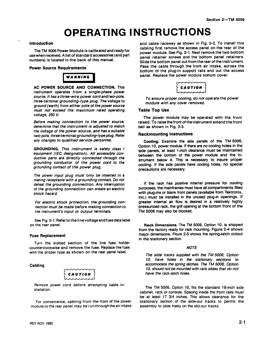
Fig -3 . TM 5006 bottom view
Operating Instructions-TM
TM 5006, overall dimensions REV NOV
WA RN I N G
F19 -5. Rack latch hole
Rear Panel
Equired
AC K
L STD
Spaci N G S Paci N G
NOM I NAL Clea RAN CE To in Strument on TOP or Bottom
Stop Latch Holes
Operating Instructions-TM
To Remove
Operating Instructions-ΤΜ
Power supply High power Family key
Signal source
Avertissemert
ITF2950-01 Fig . Ζ-1 . Ponneau arri δre do TM
Instructions d υtάθάsατίοη TM
Vis de fixation
Vls do fixation Do ραηη eαυ inferieur
Instructions d utilisation ΤΜ
Installation et retrait des tiroirs
Rabattablε De masse TF2950-02 Fig -2. Vue de face du ΤΜ
Compatibilite avec les autres families
REV ΝΟ V
Instructio ns dutilisation σ 7 Μ
Barre de support
French
La rάsistance de Ιemballage est de 62 Kg/cm2 French
Instructions de reemballage
Instrument, et la description du defout constatά
Fre n ch
ΊηfkWυι
Espacem ent conforme Box η ormes MIL STD
Espacement confοrme box normes ΕΙΑ R S310
Mo ntage dans un e baie profo nde de la baie
Inst ructio n s d u tilisation TM Trou du verrou
De fixation ά Ν b aie
Fren c h 2
ΤF 12259-212950-09Α
Poor ίter In TM 6006 do α Υαίe
French 2- 1
Instructions d utilisatio n TM Detrompeu r En coc he
De la famille TM
Rainu re Supέι ie ure TF2823-22950-10
German
Warnun G
Nmerkung
Fir Netzkabel
Bedienungsanleit ung TM
Ab deck platte Ηυι mit Option
Hatteschraube Bode nplatte
NM E Rkun G
Vorsichτ
Bild 2-3 . TM 5006 Ansic ht d e r Unte rseite Germa n
Page
GerliterUckseite
Abstxnde BST NDE
MIL STD
Nominal Abstand
Retma
EINRASTL6CHER
Schrausen
Feststehender
Laschen
EI NS Etzen
HE Rausnehmen
Be dienu ngsonie ίtung TM
German 2- 1
Bedie nu ngsa n leitun g TM
SP ERR E USS Paru NG Bere
TJ H RU NGS
+ε F ~ Ο
ΤΜ5006Α2 ιlτΜ5000% J
Τι ~3
+t9 εόύ q -~, ι L~ ι ~ τιά
ΦΑΜ
7i V -f!ε $Q&1 ΙΙ ttέ ~ λΜ &1S$ ι k &1 Τ -1* ό
A N
ΤΙΜ 50062 $SίΟΜΒΑ
~ ΜΜ 2 7i%χ 22-3 1R1~ ά ~tλ ~ ι J ι Apa nese 2
Ja panese
ΤΜ500691 L
ΤΜ 5006 W ΙίΜIRVA Ζ214-1593-02
~# λτ
Ζι σ
Japanese
~5 r 1 F $β
R4 λ 7-f ΚΙ*Μ2
ΤΜ 5006 Μ Ιί #REBA
5Υη λ -5- Γ ΚΡΜ
844τ ~~~C ι `7 r η
+ ι
ΤΜ 500641 1Μ #ROM
07 ι -4 7ί Γ F t λ 5Γ = h5 ι -7 Οχ t ό ht+7 P L # Τ
\ ιtl % ΤJ τ AL Ιτα
JA N
ΤΛΛ 500β MIJ W#ά IP 12 2 Φ JJ * σ V19i Τ
Page
Control Logic and Drivers
Line Selector and 60 Hk Transformer
Rectifiers and Filters
+α ν
Full
Theory of Operatio n-ΤΜ
Wave bri dge rectif ie r fo r 220 V ac li ne
Output Regulator
Control Ci rc uit Regulator
Theory ο1 Operatio n-ΤΜ
Overvoltage and Overcurτent Detectors
Theory of Operation-TM
Mai n Interface Ο3
All 0.3 Ω
Test Loads for the Performance Check Procedure
All 1 Ω
Calibration-TM
Perfo Rmance C Heck S Ummary Sheet
TEK Tronix DM
Suggested Test Equipment
CHECK-that the supply reads from +7 .6 V tb
+8 .5 Procedure Remove all connections
Cali brati on-ΤΜ
Calibrati on-ΤΜ
Services Available
Adjustment Access
Power Li mit Adjustment
REV Νον
240V/13A 240V/10A
Line Voltage Selectio n
Stati c Se nsitive Components
North American Un iversal European Australian
TTL
Elative Suscep Tibi Lity to Static Disc Harge Damag E
ECL
Index
Multipin Connectors
Semiconductors
Mai ntenance-ΤΜ
Outer panel removal
Maintenance-TIM
Maintenance-ΤΜ
REV sεετ
Maintenance-TM
111Uιι1111 111111111- .111111ιιιιιιιυιιιιιιιιιιιι
Fig 1 0 . Attaching screws on bottom of mainframe
Remove these screws to
Page
Fig 1 3. Screws holding heat sink to circuit board
Fig -14 . Transformer assembly attaching screws
2950-31
PWR Indicator
Pin Assig nm e nts
PWR
FUN Ctio N CO N Tacts CO N Tacts FUN Ctio N
Nrfd
ΑΤΝ
IFC
Ndac
System Design Directions
Wire Use
Options-TM
Abbreviations conform to American National Standard Υ1
Example α Component number Α23R1234 Assembly number
Read Resistor 1234 of Subassembly 2 of Assembly
Mfr
Ζμαν a N D Assoc I AT E S
CR OSS in D E X MFR. COD E Number to M a NUF ACT Urer
Manufacturer Address
ΜΑ205ΕΙ 04ΜΑΑ
QTY
REV OCT
AID
Nfr
Component No
COIL,RFFIXΦ , lMH
AlIR1600
AlIR1852
AlIR1931
Prcν Retri Ggera BLE
RES, VAR,NONWW TRMR, IK OHM,0 .5W
ND Ings
Invert ER,BURN-
Name & Description
SY N C G Ener ATO R
Overcurrent Detectors
CONTROL. ισν
Circuit Regulatorto
Output Regulator Circu I TRY
T Erconne CT OA R D BL OC K D I AG R a M
ZA Nsformer
JE Sele CTO R
ECT I F I ER S L T ERS
REV N O V
ΙΟΝ G RID
Parts Locat
INS
DC Power Supply Ο1
BOA R D
Number
~ Β Ι C ~ D ~ Ε ~ F ~ Η
23 Α2 R
Static Se nsitive Devices
R1851
C2140 C2150 C2151 C2160 C2230 C2231 C2232
F2340 2330 01730 01731 2240 R1830
R1832
Pi n
Cloc k
+10
Clock U1840 B
INK
OET Ectors
Grim ~~
Ubass Embly UI7
DC PO WER S Uppl Y RE G UL ATO R ΟJS
ΘΘΚ
ΑNU M be RY~
A23 A2 R
Main I n te ι taeι
Ca rd Assy Α10
Assy Α
C1410 550
C1011 1530 C1012 C1020 C1021 1520 C1110 P1530 C1111 153Ο
C1312 520
C1320
~3--~
~ ~3--~`
INT Erface
23Α Α2 R
REN
GN D
NRF D
~ \
ΙνΙ
108
CO MP O NEN T Number E XAM PLE
~L5 Ι
~ Ι νΙ
EN on
No ιι--=WEll-z ι ~~ ιι--i ,~. ι ιι
= = ~ ~ θ
= =
ΒSΚΤ
TPG
MA NUF ACT Urer
Rubber
MFR. COD E Number to
Index
Page
Page
REV APR
REV APR
Attaching Parts
Index
214-1593-02
KEY,CON 1 Plznckt Βoard CON
20ΜΜ FUS ES
THK,STL END Attaching PA RTS
Attaching
END Attaching Parts
RεΡι
Serial /Assen bly No
Q600, ο6ιο RΕΡι
Ιι0
CO I L,RF see All L1440 Repl
AR SL S ECT,DWR ΕΧΤ 12 .625 L , W/Ο Hardware Attaching Parts
REV NOV
Option
REV APR
Hrr
Tektronix
Qty