Power Module
Revised OCT
Serial
First Printing JA N
EK T R O N IX, ΤΕΚ , SCO PE-M O B I LE
Μι τεπιΙδ1ι~ τ±#,I R Uτ1 15 491-Τ ti T3tA
ST Rument S ER IA L Number S
Vii
Sect i on 1 Specificatio N
Operati NG I Nstructions
Chapitre 2 Inst RU Ctio NS D Utilisatio N
Contents
Illustrations
Parts
Change I Nformation
System Des i gn Directions
Unsolder these wires to remove
Dc power supply board Α11
Dime sio
211
Α10 Comp onent R eferen ce Chart
REV JAN
Terms As Marked on Equipment
Terms 1η This Manual
Do Not Operate Wit hout Covers
Ervice Safety Summary
Te rm es utilisέs da ns ce manuel
Re ρdres gravά s ωι Ι a pp areil
So urce dalime ntatio n
Ise ά la masse de Ι appareil
Ne d6pannez pas se υl
Source dali mentation
Diese m Handbuch
Markίerungen auf dem Gedit
Sc hutzerdungskonta kt
Netzs pannungsversorgung
Sicherheitsangaben FUR DEN Service
1983
TiΟ ib 3 1J10- Miff.-c,-4
Vrms
ΜΡυ J 3Υ η eΧι t α c Lb C45 h -1t ο
~F ι ο
S3A~0 a
~ ι ι ~~ Ζι ~3 θ ι
295ϋ00 TM 5006 Power Modu le ADD JAN
Supplies
Electrical Characteristics
Pard
Specification-TM Characteristics
Type
Maximum floati ng voltage
Seri ES Pass Transistors
Specification-TM Cont Characteristi cs Voltage Ranges
Maximum power consumption Fuse Data
Source Power Requirements Iscellaneous
100 V, 110 V, 120 V ranges 200 ν, 220 V, 240 V ranges
EMC
Envi Nmental Character Istics
Physical Characteristics
III
ΙΝΑ RM 1 Ν G
Νοτε
REV Sept
No ΤΕ
Fig -3 . TM 5006 bottom view
TM 5006, overall dimensions REV NOV
Operating Instructions-TM
F19 -5. Rack latch hole
Rear Panel
Equired
WA RN I N G
L STD
Spaci N G S Paci N G
NOM I NAL Clea RAN CE To in Strument on TOP or Bottom
AC K
Operating Instructions-TM
Stop Latch Holes
Operating Instructions-ΤΜ
To Remove
Signal source
Power supply High power Family key
Avertissemert
Instructions d υtάθάsατίοη TM
Vis de fixation
Vls do fixation Do ραηη eαυ inferieur
ITF2950-01 Fig . Ζ-1 . Ponneau arri δre do TM
Installation et retrait des tiroirs
Rabattablε De masse TF2950-02 Fig -2. Vue de face du ΤΜ
Compatibilite avec les autres families
Instructions d utilisation ΤΜ
Barre de support
Instructio ns dutilisation σ 7 Μ
REV ΝΟ V
French
Instrument, et la description du defout constatά
Instructions de reemballage
La rάsistance de Ιemballage est de 62 Kg/cm2 French
ΊηfkWυι
Espacem ent conforme Box η ormes MIL STD
Espacement confοrme box normes ΕΙΑ R S310
Fre n ch
Inst ructio n s d u tilisation TM Trou du verrou
De fixation ά Ν b aie
Fren c h 2
Mo ntage dans un e baie profo nde de la baie
Poor ίter In TM 6006 do α Υαίe
ΤF 12259-212950-09Α
Instructions d utilisatio n TM Detrompeu r En coc he
De la famille TM
Rainu re Supέι ie ure TF2823-22950-10
French 2- 1
Nmerkung
Warnun G
German
Bedienungsanleit ung TM
Ab deck platte Ηυι mit Option
Hatteschraube Bode nplatte
Fir Netzkabel
Vorsichτ
NM E Rkun G
Bild 2-3 . TM 5006 Ansic ht d e r Unte rseite Germa n
Page
GerliterUckseite
MIL STD
Nominal Abstand
Retma
Abstxnde BST NDE
Schrausen
Feststehender
Laschen
EINRASTL6CHER
Be dienu ngsonie ίtung TM
HE Rausnehmen
EI NS Etzen
Bedie nu ngsa n leitun g TM
SP ERR E USS Paru NG Bere
TJ H RU NGS
German 2- 1
ΤΜ5006Α2 ιlτΜ5000% J
Τι ~3
+t9 εόύ q -~, ι L~ ι ~ τιά
+ε F ~ Ο
ΦΑΜ
7i V -f!ε $Q&1 ΙΙ ttέ ~ λΜ &1S$ ι k &1 Τ -1* ό
~ ΜΜ 2 7i%χ 22-3 1R1~ ά ~tλ ~ ι J ι Apa nese 2
ΤΙΜ 50062 $SίΟΜΒΑ
A N
Ja panese
ΤΜ 5006 W ΙίΜIRVA Ζ214-1593-02
~# λτ
Ζι σ
ΤΜ500691 L
~5 r 1 F $β
Japanese
ΤΜ 5006 Μ Ιί #REBA
5Υη λ -5- Γ ΚΡΜ
844τ ~~~C ι `7 r η
R4 λ 7-f ΚΙ*Μ2
ΤΜ 500641 1Μ #ROM
07 ι -4 7ί Γ F t λ 5Γ = h5 ι -7 Οχ t ό ht+7 P L # Τ
\ ιtl % ΤJ τ AL Ιτα
+ ι
ΤΛΛ 500β MIJ W#ά IP 12 2 Φ JJ * σ V19i Τ
JA N
Page
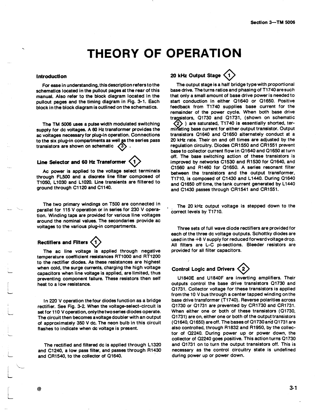
Rectifiers and Filters
Line Selector and 60 Hk Transformer
Control Logic and Drivers
+α ν
Theory of Operatio n-ΤΜ
Wave bri dge rectif ie r fo r 220 V ac li ne
Output Regulator
Full
Overvoltage and Overcurτent Detectors
Theory ο1 Operatio n-ΤΜ
Control Ci rc uit Regulator
Mai n Interface Ο3
Theory of Operation-TM
All 1 Ω
Test Loads for the Performance Check Procedure
All 0.3 Ω
Perfo Rmance C Heck S Ummary Sheet
Calibration-TM
Suggested Test Equipment
TEK Tronix DM
Cali brati on-ΤΜ
+8 .5 Procedure Remove all connections
CHECK-that the supply reads from +7 .6 V tb
Services Available
Adjustment Access
Power Li mit Adjustment
Calibrati on-ΤΜ
REV Νον
Line Voltage Selectio n
Stati c Se nsitive Components
North American Un iversal European Australian
240V/13A 240V/10A
ECL
Elative Suscep Tibi Lity to Static Disc Harge Damag E
TTL
Multipin Connectors
Semiconductors
Mai ntenance-ΤΜ
Index
Maintenance-TIM
Outer panel removal
Maintenance-ΤΜ
111Uιι1111 111111111- .111111ιιιιιιιυιιιιιιιιιιιι
Maintenance-TM
REV sεετ
Remove these screws to
Fig 1 0 . Attaching screws on bottom of mainframe
Page
Fig -14 . Transformer assembly attaching screws
Fig 1 3. Screws holding heat sink to circuit board
Pin Assig nm e nts
PWR Indicator
2950-31
FUN Ctio N CO N Tacts CO N Tacts FUN Ctio N
PWR
ΑΤΝ
IFC
Ndac
Nrfd
Wire Use
System Design Directions
Options-TM
Read Resistor 1234 of Subassembly 2 of Assembly
Example α Component number Α23R1234 Assembly number
Abbreviations conform to American National Standard Υ1
Mfr
Manufacturer Address
CR OSS in D E X MFR. COD E Number to M a NUF ACT Urer
Ζμαν a N D Assoc I AT E S
QTY
REV OCT
AID
ΜΑ205ΕΙ 04ΜΑΑ
Nfr
Component No
AlIR1600
AlIR1852
AlIR1931
COIL,RFFIXΦ , lMH
RES, VAR,NONWW TRMR, IK OHM,0 .5W
ND Ings
Invert ER,BURN-
Prcν Retri Ggera BLE
Name & Description
SY N C G Ener ATO R
CONTROL. ισν
Circuit Regulatorto
Output Regulator Circu I TRY
Overcurrent Detectors
ZA Nsformer
JE Sele CTO R
ECT I F I ER S L T ERS
T Erconne CT OA R D BL OC K D I AG R a M
ΙΟΝ G RID
REV N O V
Parts Locat
DC Power Supply Ο1
BOA R D
Number
INS
~ Β Ι C ~ D ~ Ε ~ F ~ Η
Static Se nsitive Devices
23 Α2 R
C2140 C2150 C2151 C2160 C2230 C2231 C2232
F2340 2330 01730 01731 2240 R1830
R1832
R1851
Cloc k
+10
Clock U1840 B
Pi n
Grim ~~
OET Ectors
INK
DC PO WER S Uppl Y RE G UL ATO R ΟJS
ΘΘΚ
ΑNU M be RY~
Ubass Embly UI7
Main I n te ι taeι
A23 A2 R
Assy Α
Ca rd Assy Α10
C1011 1530 C1012 C1020 C1021 1520 C1110 P1530 C1111 153Ο
C1312 520
C1320
C1410 550
~ ~3--~`
~3--~
23Α Α2 R
INT Erface
NRF D
GN D
REN
108
ΙνΙ
~ \
~ Ι νΙ
~L5 Ι
CO MP O NEN T Number E XAM PLE
No ιι--=WEll-z ι ~~ ιι--i ,~. ι ιι
EN on
= =
= = ~ ~ θ
TPG
ΒSΚΤ
MFR. COD E Number to
Rubber
MA NUF ACT Urer
Index
Page
Page
REV APR
REV APR
Index
214-1593-02
KEY,CON 1 Plznckt Βoard CON
Attaching Parts
THK,STL END Attaching PA RTS
Attaching
END Attaching Parts
20ΜΜ FUS ES
Serial /Assen bly No
Q600, ο6ιο RΕΡι
Ιι0
RεΡι
CO I L,RF see All L1440 Repl
AR SL S ECT,DWR ΕΧΤ 12 .625 L , W/Ο Hardware Attaching Parts
Option
REV NOV
REV APR
Qty
Tektronix
Hrr