3 Installation | Model 3300PA | |
|
|
|
|
|
|
|
|
|
pump
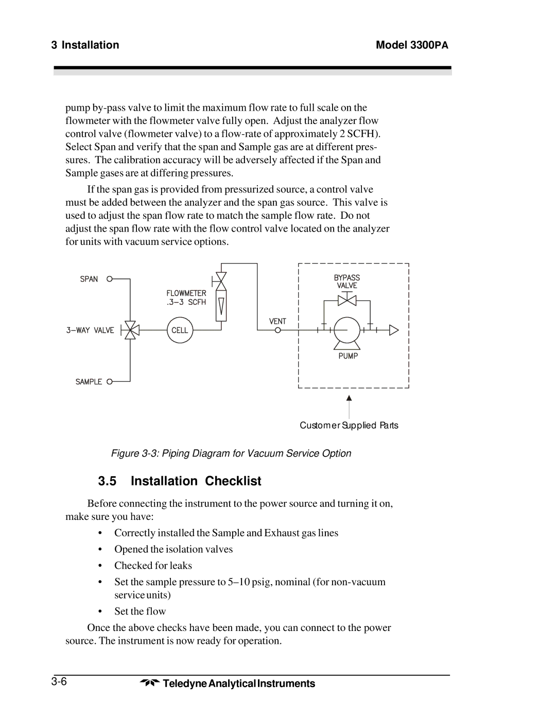
If the span gas is provided from pressurized source, a control valve must be added between the analyzer and the span gas source. This valve is used to adjust the span flow rate to match the sample flow rate. Do not adjust the span flow rate with the flow control valve located on the analyzer for units with vacuum service options.
Customer Supplied Parts
Figure 3-3: Piping Diagram for Vacuum Service Option
3.5Installation Checklist
Before connecting the instrument to the power source and turning it on, make sure you have:
•Correctly installed the Sample and Exhaust gas lines
•Opened the isolation valves
•Checked for leaks
•Set the sample pressure to
•Set the flow
Once the above checks have been made, you can connect to the power source. The instrument is now ready for operation.
Teledyne Analytical Instruments |