Manuals
/
Teledyne
/
TV and Video
/
TV Video Accessories
Teledyne
instruction manual
HPM-2002-OBEVacuum Gauge
Models:
HPM-2002-OBE
1
38
39
39
Download
39 pages
52.25 Kb
32
33
34
35
36
37
38
39
Troubleshooting
Specifications
Install
Diagrams and Drawings
Restore Factory Defaults
Turnaround Delay
Warranty
Reset / Restore Commands
Advanced Setup Guide
Command Syntax
Page 38
Image 38
HPM-2002-OBEVacuum
Gauge
Page 38 of 39
Page 37
Page 39
Page 38
Image 38
Page 37
Page 39
Contents
Teledyne Hastings
Manual Print History
Table of Contents
Troubleshooting
HPM-2002-OBE Analog Output Module
Features
Model 2002 Sensors
HPM-2002-OBE Analog Output 4-20mA Module
HPM-2002-OBE DeviceNet Module
Specifications
HPM-2002-OBE RS232/485 Output Module
Receiving Inspection
Transducer Installation
OBE Module Installation
Quick Start
Initial Operation
Pin Volt 20 mA RS232/485
High and Low Set Point Modes
Analog Output
Overall Functional Description
Run Mode
Cal Mode
Analog Output
GAS Mode
Gas Selection Table
HPM-2002-OBEVacuum Gauge
Analog Output 4-20mA
Cal Mode
Analog Output 4-20mA
HPM-2002-OBEVacuum Gauge
Command Syntax
RS232/485 With Display
Interrogation Commands
Paramater Modification Commands
Calibration Adjustment Commands
Reset / Restore Commands
Default RS232/485 Specifications
Device Status
Modular Connector Pinout R2-232 RJ-11 connector on left side
Modular Connector Pinout RS-485
Run Mode
DeviceNet TM
DeviceNet description
Atmosphere Coefficient Adjustment
Zero Coefficient Adjustment
Midrange Coefficient Adjustment
Calibration of the HPM-2002-OBE
Theory of Operation
Piezoresistive Sensor
Vo = SPV+V1
HPM-2002-OBEVacuum Gauge
Es = K ∆T Am/L
Pirani Sensor
Et = Es + Er + Eg
Er = σεTh4-Ta4As
HPM-2002-OBEVacuum Gauge
Dual Sensor Operation
Eg = Kg ∆T As/∆x
Eg = arLt273/Th1/2Th-TaAgP
HPM-2002-OBEVacuum Gauge
Advanced Setup Guide
RS485 Address
Baud Rate
Turnaround Delay
Restore Eeprom
Data Bits/Parity Bits/Stop Bits
Software Reset
Restore Calibration
Restore Factory Defaults
Frequently Asked Questions Why does my display read, Err1?
Why does my display read, . U?
Why does my display read, U.U?
Why does my display read, U .?
What are Err3, Err5, Err6 and Err7?
Warranty Repair Policy
Non-Warranty Repair Policy
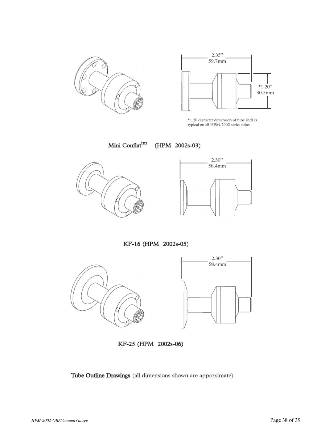
Diagrams and Drawings
HPM-2002-OBEVacuum Gauge
HPM-2002-OBEVacuum Gauge
Top
Page
Image
Contents