Manuals
/
Teledyne
/
TV and Video
/
TV Video Accessories
Teledyne
instruction manual
HPM-2002-OBEVacuum Gauge
Models:
HPM-2002-OBE
1
39
39
Download
39 pages
52.25 Kb
32
33
34
35
36
37
38
39
Troubleshooting
Specification
Install
Diagrams and Drawings
Restore Factory Defaults
Turnaround Delay
Warranty
Reset / Restore Commands
Advanced Setup Guide
Command Syntax
Page 39
Image 39
HPM-2002-OBEVacuum
Gauge
Page 39 of 39
Page 38
Page 39
Page 39
Image 39
Page 38
Page 39
Contents
Teledyne Hastings
Manual Print History
Table of Contents
Troubleshooting
HPM-2002-OBE Analog Output 4-20mA Module
Features
Model 2002 Sensors
HPM-2002-OBE Analog Output Module
Specifications
HPM-2002-OBE RS232/485 Output Module
HPM-2002-OBE DeviceNet Module
Quick Start
Transducer Installation
OBE Module Installation
Receiving Inspection
Pin Volt 20 mA RS232/485
Initial Operation
Analog Output
Overall Functional Description
High and Low Set Point Modes
Cal Mode
Run Mode
GAS Mode
Gas Selection Table
Analog Output
HPM-2002-OBEVacuum Gauge
Analog Output 4-20mA
Cal Mode
Analog Output 4-20mA
HPM-2002-OBEVacuum Gauge
RS232/485 With Display
Command Syntax
Paramater Modification Commands
Interrogation Commands
Reset / Restore Commands
Calibration Adjustment Commands
Device Status
Default RS232/485 Specifications
Modular Connector Pinout RS-485
Modular Connector Pinout R2-232 RJ-11 connector on left side
Run Mode
DeviceNet description
DeviceNet TM
Calibration of the HPM-2002-OBE
Zero Coefficient Adjustment
Midrange Coefficient Adjustment
Atmosphere Coefficient Adjustment
Theory of Operation
Vo = SPV+V1
Piezoresistive Sensor
HPM-2002-OBEVacuum Gauge
Er = σεTh4-Ta4As
Pirani Sensor
Et = Es + Er + Eg
Es = K ∆T Am/L
HPM-2002-OBEVacuum Gauge
Eg = Kg ∆T As/∆x
Eg = arLt273/Th1/2Th-TaAgP
Dual Sensor Operation
HPM-2002-OBEVacuum Gauge
RS485 Address
Advanced Setup Guide
Data Bits/Parity Bits/Stop Bits
Turnaround Delay
Restore Eeprom
Baud Rate
Frequently Asked Questions Why does my display read, Err1?
Restore Calibration
Restore Factory Defaults
Software Reset
What are Err3, Err5, Err6 and Err7?
Why does my display read, U.U?
Why does my display read, U .?
Why does my display read, . U?
Non-Warranty Repair Policy
Warranty Repair Policy
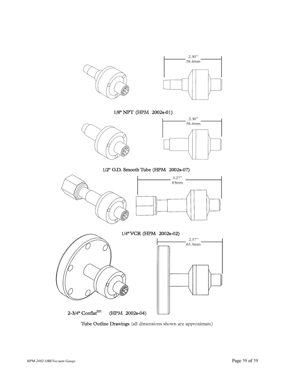
Diagrams and Drawings
HPM-2002-OBEVacuum Gauge
HPM-2002-OBEVacuum Gauge
Top
Page
Image
Contents