Model |
|
| Operational Theory 2 | |
|
|
|
|
|
|
|
|
|
|
|
|
|
|
|
|
|
|
|
|
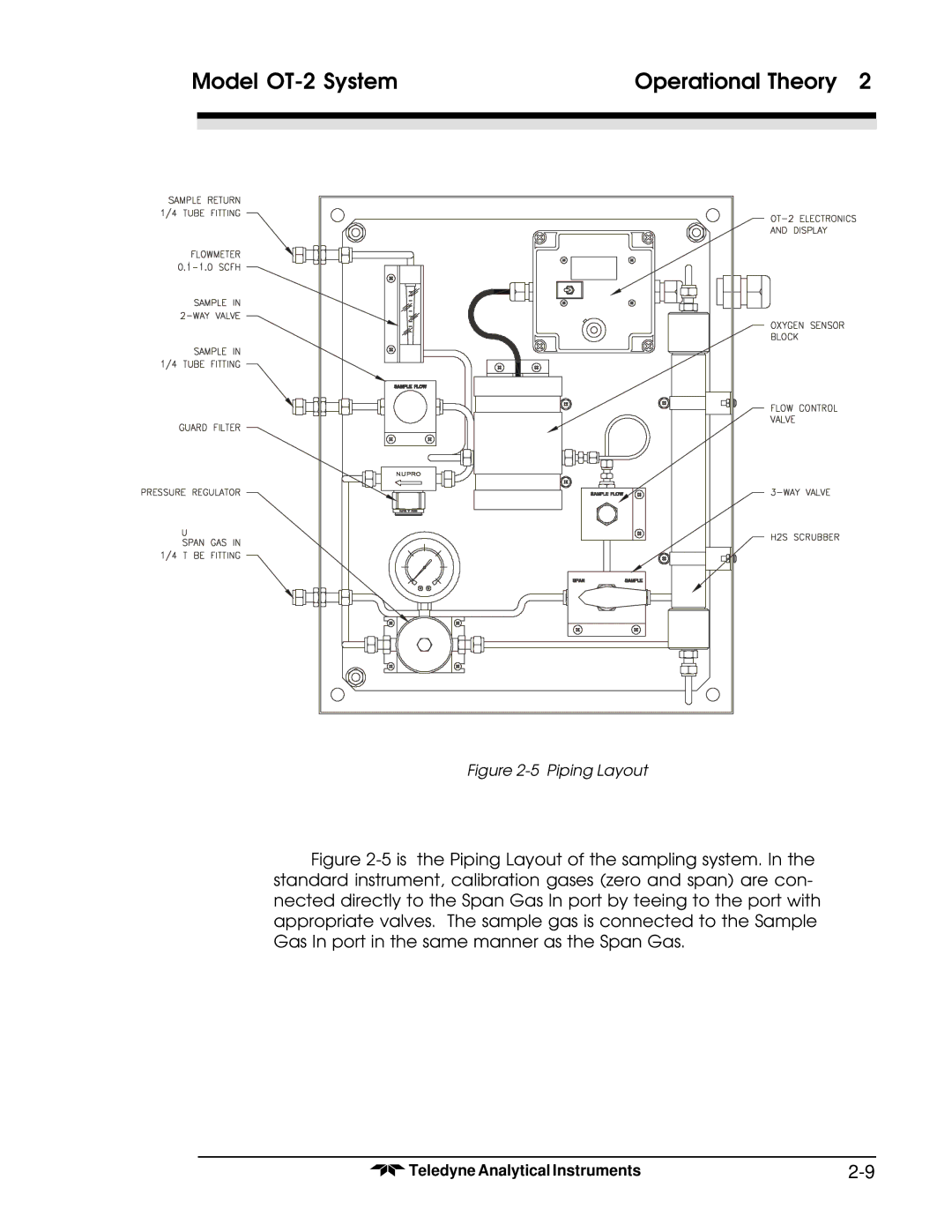
Figure 2-5 Piping Layout
Figure 2-5 is the Piping Layout of the sampling system. In the standard instrument, calibration gases (zero and span) are con- nected directly to the Span Gas In port by teeing to the port with appropriate valves. The sample gas is connected to the Sample Gas In port in the same manner as the Span Gas.
Teledyne Analytical Instruments |