Model OT-2 System

Operation 3


Transmitter Cover Screws (4 places)

To Sensor

Display

Span

Electrical

Connections

Figure 3-3 Front View of Transmitter

System Power Requirements:

The Model OT-2 System requires a 12 VDC (nominal), reverse polarity protected power source.

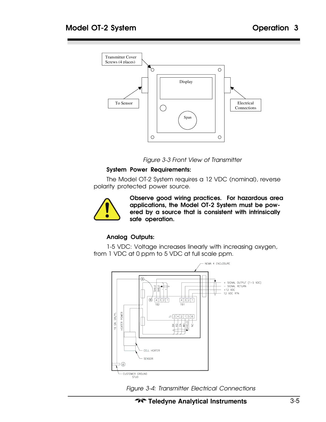
Observe good wiring practices. For hazardous area applications, the Model OT-2 System must be pow- ered by a source that is consistent with intrinsically safe operation.

Analog Outputs:

1-5 VDC: Voltage increases linearly with increasing oxygen, from 1 VDC at 0 ppm to 5 VDC at full scale ppm.

Figure 3-4: Transmitter Electrical Connections

Teledyne Analytical Instruments

3-5

Page 23
Image 23
Teledyne OT-2 operating instructions Front View of Transmitter