Model | Operational Theory 2 | |
|
|
|
|
|
|
Refer to Figure
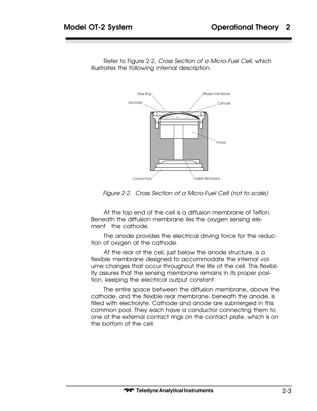
Figure 2-2. Cross Section of a Micro-Fuel Cell (not to scale)
At the top end of the cell is a diffusion membrane of Teflon. Beneath the diffusion membrane lies the oxygen sensing ele-
The anode provides the electrical driving force for the reduc- tion of oxygen at the cathode.
At the rear of the cell, just below the anode structure, is a flexible membrane designed to accommodate the internal vol- ume changes that occur throughout the life of the cell. This flexibil- ity assures that the sensing membrane remains in its proper posi- tion, keeping the electrical output constant.
The entire space between the diffusion membrane, above the cathode, and the flexible rear membrane, beneath the anode, is filled with electrolyte. Cathode and anode are submerged in this common pool. They each have a conductor connecting them to one of the external contact rings on the contact plate, which is on the bottom of the cell.
Teledyne Analytical Instruments |