Percent Oxygen Analyzer | Operational Theory | |
|
|
|
Probes of 1000 mm (40”) normally have sufficient length for any installation. Customers requiring probes longer than 1500 mm (59”) are supplied with a flow guide tube that uses the flue velocity to pull flue gas through a filter at the sensing tip and exhaust it near the flue wall.
2.2.1 Probe Configuration
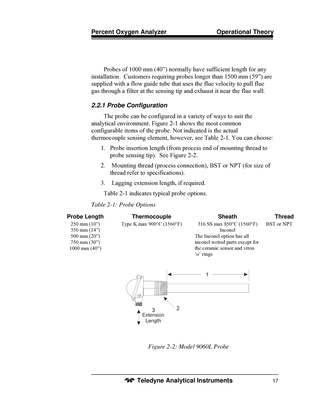
The probe can be configured in a variety of ways to suit the analytical environment. Figure
1.Probe insertion length (from process end of mounting thread to probe sensing tip). See Figure
2.Mounting thread (process connection), BST or NPT (for size of thread refer to specifications).
3.Lagging extension length, if required.
Table
Table 2-1: Probe Options
Probe Length | Thermocouple | Sheath | Thread |
250 mm (10”) Type K max 900°C (1560°F)
350 mm (14”)
500 mm (20”)
750 mm (30”)
1000 mm (40”)
316 SS max 850°C (1560°F) | BST or NPT |
Inconel |
|
The Inconel option has all |
|
inconel wetted parts except for |
|
the ceramic sensor and viton |
|
‘o’ rings |
|
Figure 2-2: Model 9060L Probe
Teledyne Analytical Instruments | 17 |