Percent Oxygen Analyzer | Installation | |
|
|
|
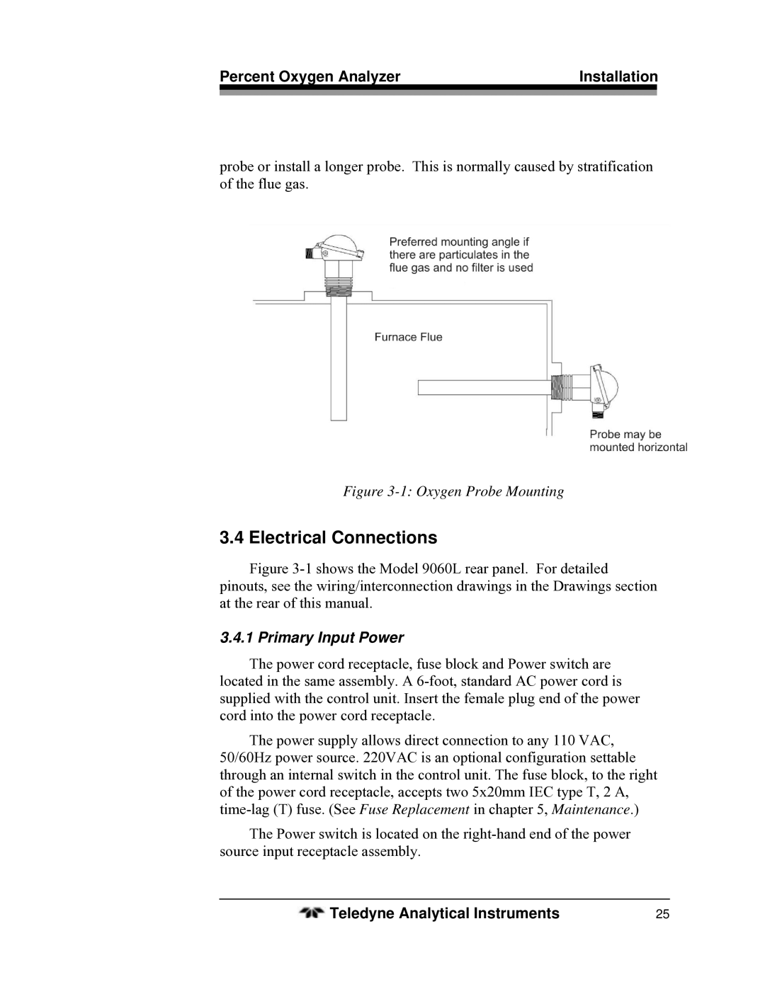
probe or install a longer probe. This is normally caused by stratification of the flue gas.
Figure 3-1: Oxygen Probe Mounting
3.4 Electrical Connections
Figure 3-1 shows the Model 9060L rear panel. For detailed pinouts, see the wiring/interconnection drawings in the Drawings section at the rear of this manual.
3.4.1 Primary Input Power
The power cord receptacle, fuse block and Power switch are located in the same assembly. A
The power supply allows direct connection to any 110 VAC, 50/60Hz power source. 220VAC is an optional configuration settable through an internal switch in the control unit. The fuse block, to the right of the power cord receptacle, accepts two 5x20mm IEC type T, 2 A,
The Power switch is located on the
Teledyne Analytical Instruments | 25 |