AT Commands
“Setting the OMEGA DIP Switch” on page 13).
To facilitate this connection, the OMEGA Marwell socket adapter comes with an
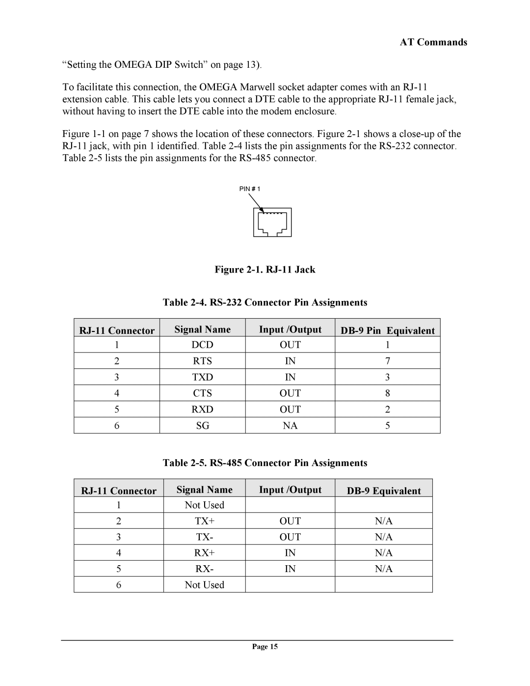
Figure 1-1 on page 7 shows the location of these connectors. Figure 2-1 shows a close-up of the RJ-11 jack, with pin 1 identified. Table 2-4 lists the pin assignments for the RS-232 connector. Table 2-5 lists the pin assignments for the RS-485 connector.
PIN # 1
Figure 2-1. RJ-11 Jack
Table 2-4. RS-232 Connector Pin Assignments
| Signal Name | Input /Output |
|
1 | DCD | OUT | 1 |
|
|
|
|
2 | RTS | IN | 7 |
|
|
|
|
3 | TXD | IN | 3 |
|
|
|
|
4 | CTS | OUT | 8 |
|
|
|
|
5 | RXD | OUT | 2 |
|
|
|
|
6 | SG | NA | 5 |
|
|
|
|
Table
Signal Name | Input /Output | ||
1 | Not Used |
|
|
|
|
|
|
2 | TX+ | OUT | N/A |
3 | TX- | OUT | N/A |
|
|
|
|
4 | RX+ | IN | N/A |
5 | RX- | IN | N/A |
|
|
|
|
6 | Not Used |
|
|
Page 15