6 | Vega’s |
4 Line Setup and Description
4.1 INTRODUCTION/DEFAULTS
1 2 3 4 5 6 7 8 |
|
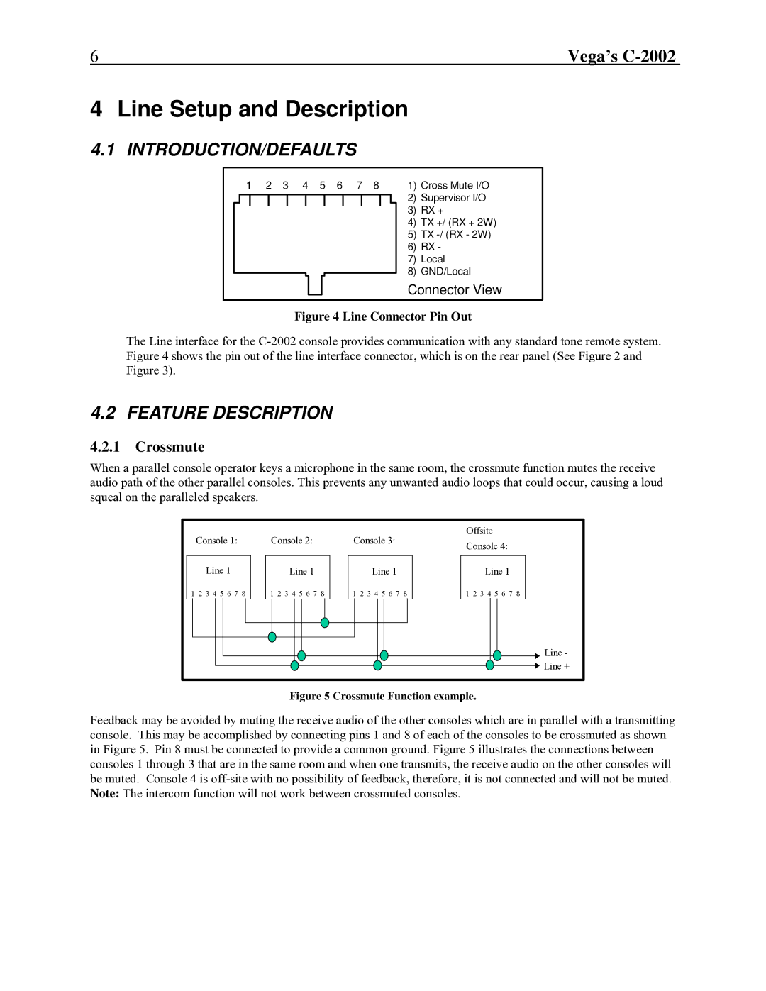
| 1) | Cross Mute I/O | ||||||||||
|
|
|
|
|
|
|
|
|
|
|
|
| 2) | Supervisor I/O |
|
|
|
|
|
|
|
|
|
|
|
|
| ||
|
|
|
|
|
|
|
|
|
|
|
|
| 3) | RX + |
|
|
|
|
|
|
|
|
|
|
|
|
| 4) | TX +/ (RX + 2W) |
|
|
|
|
|
|
|
|
|
|
|
|
| 5) | TX |
|
|
|
|
|
|
|
|
|
|
|
|
| 6) | RX - |
|
|
|
|
|
|
|
|
|
|
|
|
| 7) | Local |
|
|
|
|
|
|
|
|
|
|
|
|
| 8) | GND/Local |
Connector View
Figure 4 Line Connector Pin Out
The Line interface for the
4.2 FEATURE DESCRIPTION
4.2.1Crossmute
When a parallel console operator keys a microphone in the same room, the crossmute function mutes the receive audio path of the other parallel consoles. This prevents any unwanted audio loops that could occur, causing a loud squeal on the paralleled speakers.
Console 1: | Console 2: | Console 3: | Offsite | |
Console 4: | ||||
|
|
| ||
Line 1 | Line 1 | Line 1 | Line 1 | |
1 2 3 4 5 6 7 8 | 1 2 3 4 5 6 7 8 | 1 2 3 4 5 6 7 8 | 1 2 3 4 5 6 7 8 | |
|
|
| Line - | |
|
|
| Line + |
Figure 5 Crossmute Function example.
Feedback may be avoided by muting the receive audio of the other consoles which are in parallel with a transmitting console. This may be accomplished by connecting pins 1 and 8 of each of the consoles to be crossmuted as shown in Figure 5. Pin 8 must be connected to provide a common ground. Figure 5 illustrates the connections between consoles 1 through 3 that are in the same room and when one transmits, the receive audio on the other consoles will be muted. Console 4 is