2 | Vega’s |
2 Controls and Indicators
|
|
|
|
| |||
| Vu Muter | 11:08AM |
| ||||
|
|
|
|
| |||
1 | 2 | 3 | A | F1 | F2 | SUP | |
| ABC | DEF | |||||
4 | 5 | 6 | B | F3 | F4 | Alert | |
GHI | JKL | MNO | <- | ||||
7 | 8 | 9 | C | F5 | F6 | Chan | |
PQRS | TUV | WXYZ | <sp> | ||||
|
| ||||||
* | 0 | # | D | F7 | F8 | ALT | |
Enter | |||||||
|
|
| |||||
|
| LINE 1 |
|
| LINE 2 |
| |
Mute | RLS | SEL | Mute | RLS | SEL | ||
VOLUME | MON | IC | Transmit | ||||
|
|
|
| ||||
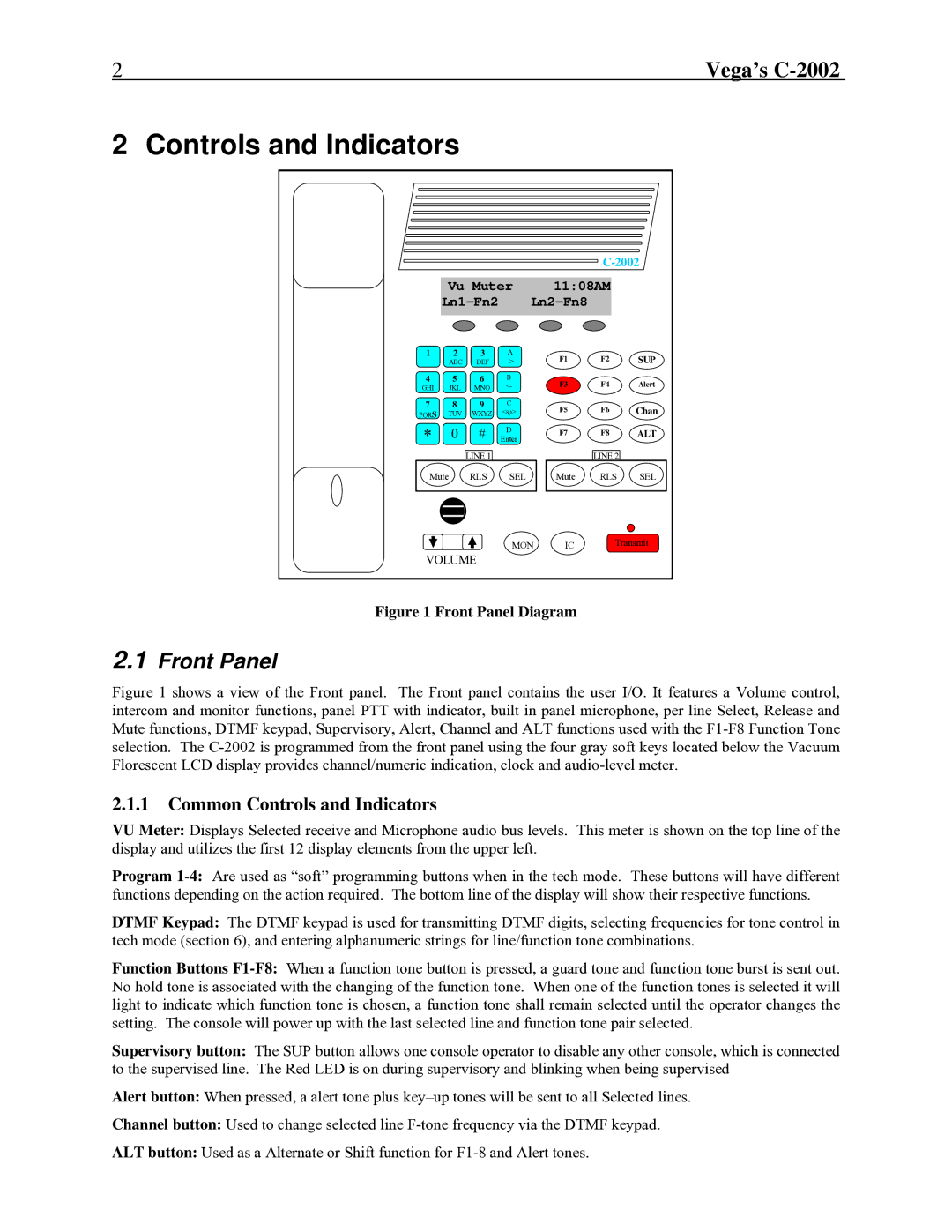
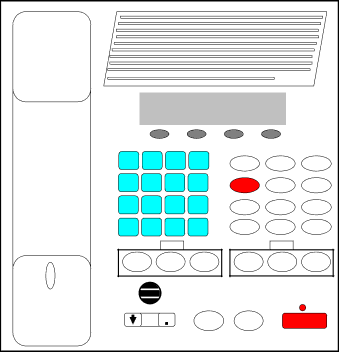
Figure 1 Front Panel Diagram
2.1Front Panel
Figure 1 shows a view of the Front panel. The Front panel contains the user I/O. It features a Volume control, intercom and monitor functions, panel PTT with indicator, built in panel microphone, per line Select, Release and Mute functions, DTMF keypad, Supervisory, Alert, Channel and ALT functions used with the F1-F8 Function Tone selection. The C-2002 is programmed from the front panel using the four gray soft keys located below the Vacuum Florescent LCD display provides channel/numeric indication, clock and audio-level meter.
2.1.1Common Controls and Indicators
VU Meter: Displays Selected receive and Microphone audio bus levels. This meter is shown on the top line of the display and utilizes the first 12 display elements from the upper left.
Program
DTMF Keypad: The DTMF keypad is used for transmitting DTMF digits, selecting frequencies for tone control in tech mode (section 6), and entering alphanumeric strings for line/function tone combinations.
Function Buttons
Supervisory button: The SUP button allows one console operator to disable any other console, which is connected to the supervised line. The Red LED is on during supervisory and blinking when being supervised
Alert button: When pressed, a alert tone plus
Channel button: Used to change selected line
ALT button: Used as a Alternate or Shift function for