Audio Channel Switch
Intercom Type Set to Telex
Selects either “IC 1 or 2" (and corresponding pins on ”IC
AUDIO
CHANNEL 1
AUTO
2
Figure 23
Audio Channel Switch
Intercom Type Set to RTS
Selects RTS channel 1 or 2 on both I/C jacks (and corresponding Pins on “I/C
Telex IN/OUT Switch
Intercom Type Set to Telex
Telex = OUT
Intercom is disconnected from the I/C jacks and corresponding “I/C
Telex = IN
Intercom is connected to I/C jacks and correspond- ing “I/C
Intercom Type Set to RTS
Setting of switch has no effect. All I/C jacks and corresponding “I/C
AUX
OFF ON
Figure 25
Auxiliary Switch
Auxiliary to I/C Switch (Program Audio)
This switch is located inside the base station. Its function is to provide a user with the ability to input a third channel of listen only audio via the “AUX” jack. This third channel of audio, usually called “Program Audio” is always heard regardless of which intercom channel the user is on. The program audio is heard only on the local base station and its beltpack.
To gain access to the switch the base station’s top cover must be taken off. Unscrew the six screws on the cover and lift off. The switch can be found be- tween the two shielded compartments (Figure 27). The switch is labeled “Aux to IC” and should nor- mally be left in the “ON” position. Unless using the “AUX” jack for program audio input. Switch to the “OFF” position if inputing program audio. The switch now disables auxilary input audio from be- ing placed on the intercom system but can be heard locally.
The auxiliary ON/OFF switch must be set to “ON” to enable input audio through the auxiliary port. The level of the program audio as heard in the back- ground of the audio channel currently switch to is controlled via the “AUX IN" level control on the front panel.
I/C
OUT TELEX IN
Figure 24
Telex In/Out Switch
Auxiliary Switch
Turns the “AUX” jack input audio on or off.
The audio out is always sent to the “Aux” jack and is unaffected by the switch position.
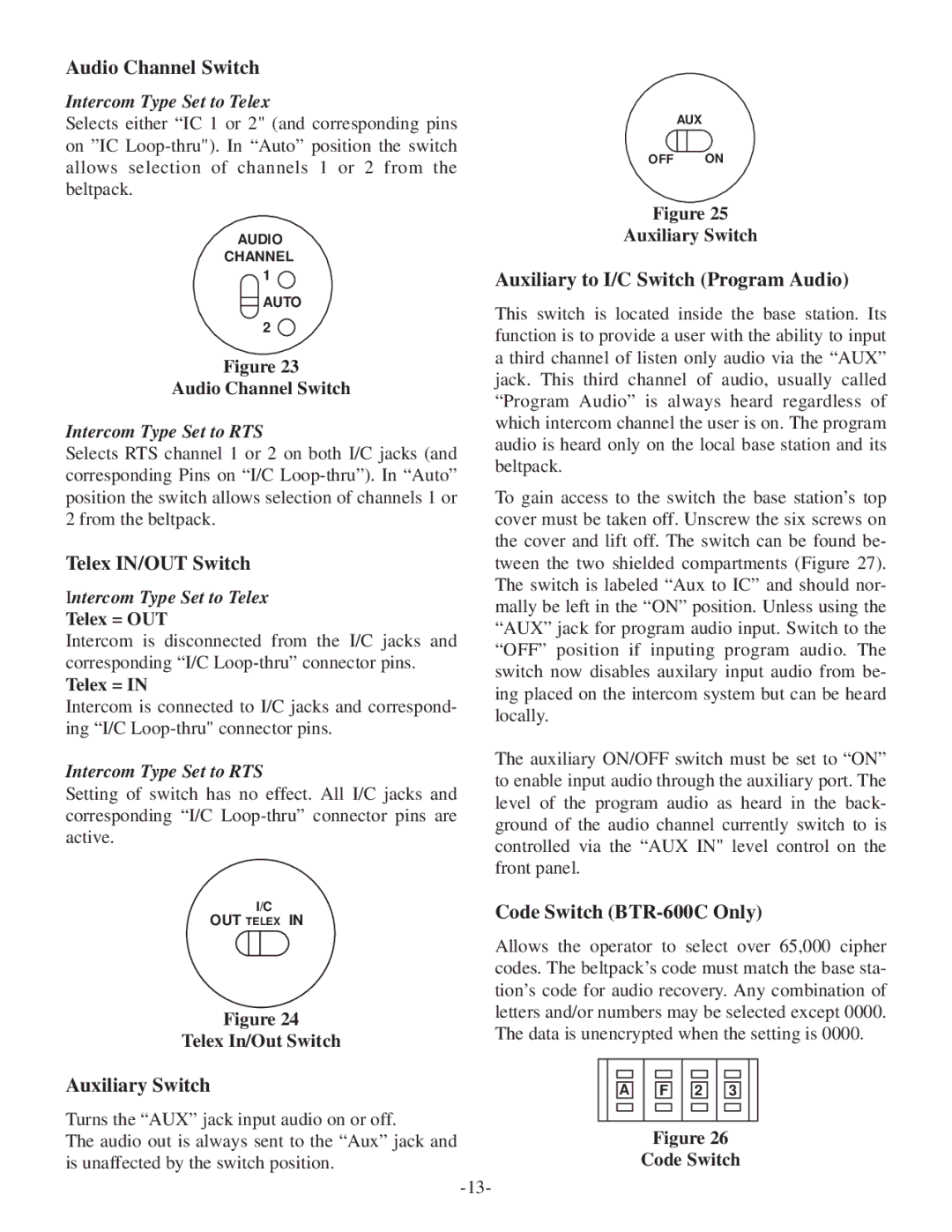
Code Switch (BTR-600C Only)
Allows the operator to select over 65,000 cipher codes. The beltpack’s code must match the base sta- tion’s code for audio recovery. Any combination of letters and/or numbers may be selected except 0000. The data is unencrypted when the setting is 0000.
A ![]()
![]() F
F ![]()
![]() 2
2 ![]()
![]() 3
3
Figure 26
Code Switch