9.& 10. Loop Thru I/C - 9 pin D-sub jack. Wired as shown.
11.See #8.
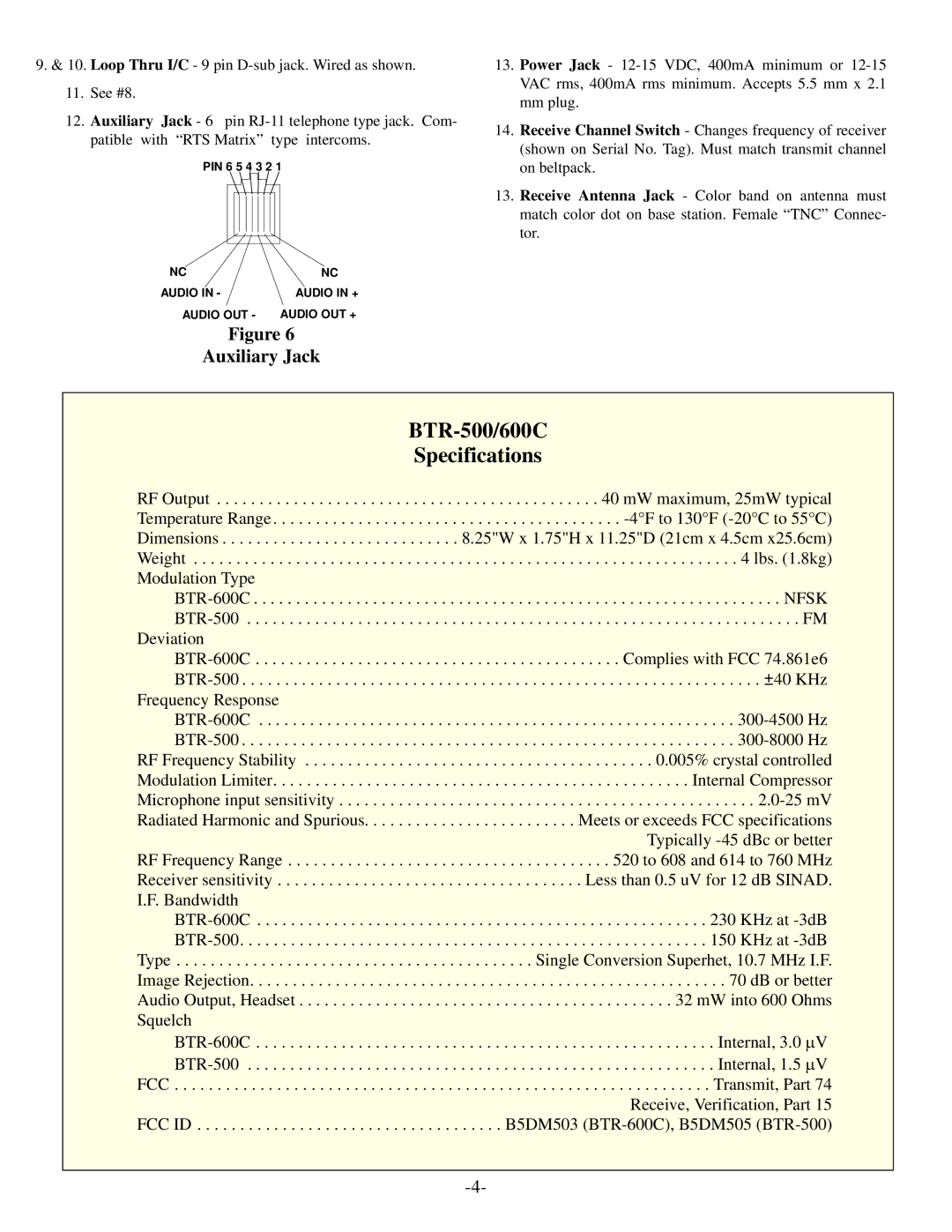
12.Auxiliary Jack - 6 pin RJ-11 telephone type jack. Com- patible with “RTS Matrix” type intercoms.
PIN 6 5 4 3 2 1
13.Power Jack - 12-15 VDC, 400mA minimum or 12-15 VAC rms, 400mA rms minimum. Accepts 5.5 mm x 2.1 mm plug.
14.Receive Channel Switch - Changes frequency of receiver (shown on Serial No. Tag). Must match transmit channel on beltpack.
13.Receive Antenna Jack - Color band on antenna must match color dot on base station. Female “TNC” Connec- tor.
NC | NC |
AUDIO IN - | AUDIO IN + |
AUDIO OUT - | AUDIO OUT + |
Figure 6
Auxiliary Jack
BTR-500/600C
Specifications
RF Output . . . . . . . . . . . . . . . . . . . . . . . . . . . . . . . . . . . . . . . . . . . . . 40 mW maximum, 25mW typical Temperature Range . . . . . . . . . . . . . . . . . . . . . . . . . . . . . . . . . . . . . . . . . -4°F to 130°F (-20°C to 55°C) Dimensions . . . . . . . . . . . . . . . . . . . . . . . . . . . . 8.25"W x 1.75"H x 11.25"D (21cm x 4.5cm x25.6cm) Weight . . . . . . . . . . . . . . . . . . . . . . . . . . . . . . . . . . . . . . . . . . . . . . . . . . . . . . . . . . . . . . . . 4 lbs. (1.8kg) Modulation Type
BTR-600C . . . . . . . . . . . . . . . . . . . . . . . . . . . . . . . . . . . . . . . . . . . . . . . . . . . . . . . . . . . . . . NFSK BTR-500 . . . . . . . . . . . . . . . . . . . . . . . . . . . . . . . . . . . . . . . . . . . . . . . . . . . . . . . . . . . . . . . . . FM
Deviation
BTR-600C . . . . . . . . . . . . . . . . . . . . . . . . . . . . . . . . . . . . . . . . . . . Complies with FCC 74.861e6 BTR-500 . . . . . . . . . . . . . . . . . . . . . . . . . . . . . . . . . . . . . . . . . . . . . . . . . . . . . . . . . . . . . ±40 KHz
Frequency Response
BTR-600C . . . . . . . . . . . . . . . . . . . . . . . . . . . . . . . . . . . . . . . . . . . . . . . . . . . . . . . . 300-4500 Hz BTR-500 . . . . . . . . . . . . . . . . . . . . . . . . . . . . . . . . . . . . . . . . . . . . . . . . . . . . . . . . . . 300-8000 Hz RF Frequency Stability . . . . . . . . . . . . . . . . . . . . . . . . . . . . . . . . . . . . . . . . . 0.005% crystal controlled
Modulation Limiter. . . . . . . . . . . . . . . . . . . . . . . . . . . . . . . . . . . . . . . . . . . . . . . . . Internal Compressor Microphone input sensitivity . . . . . . . . . . . . . . . . . . . . . . . . . . . . . . . . . . . . . . . . . . . . . . . . . 2.0-25 mV Radiated Harmonic and Spurious. . . . . . . . . . . . . . . . . . . . . . . . . Meets or exceeds FCC specifications Typically -45 dBc or better RF Frequency Range . . . . . . . . . . . . . . . . . . . . . . . . . . . . . . . . . . . . . . 520 to 608 and 614 to 760 MHz
Receiver sensitivity . . . . . . . . . . . . . . . . . . . . . . . . . . . . . . . . . . . . Less than 0.5 uV for 12 dB SINAD. I.F. Bandwidth
BTR-600C . . . . . . . . . . . . . . . . . . . . . . . . . . . . . . . . . . . . . . . . . . . . . . . . . . . . . 230 KHz at -3dB BTR-500. . . . . . . . . . . . . . . . . . . . . . . . . . . . . . . . . . . . . . . . . . . . . . . . . . . . . . . 150 KHz at -3dB Type . . . . . . . . . . . . . . . . . . . . . . . . . . . . . . . . . . . . . . . . . . Single Conversion Superhet, 10.7 MHz I.F. Image Rejection. . . . . . . . . . . . . . . . . . . . . . . . . . . . . . . . . . . . . . . . . . . . . . . . . . . . . . . . 70 dB or better Audio Output, Headset . . . . . . . . . . . . . . . . . . . . . . . . . . . . . . . . . . . . . . . . . . . . 32 mW into 600 Ohms
Squelch
BTR-600C . . . . . . . . . . . . . . . . . . . . . . . . . . . . . . . . . . . . . . . . . . . . . . . . . . . . . . Internal, 3.0 V BTR-500 . . . . . . . . . . . . . . . . . . . . . . . . . . . . . . . . . . . . . . . . . . . . . . . . . . . . . . . Internal, 1.5 V FCC . . . . . . . . . . . . . . . . . . . . . . . . . . . . . . . . . . . . . . . . . . . . . . . . . . . . . . . . . . . . . . . Transmit, Part 74 Receive, Verification, Part 15 FCC ID . . . . . . . . . . . . . . . . . . . . . . . . . . . . . . . . . . . . B5DM503 (BTR-600C), B5DM505 (BTR-500)