Beltpack
Controls and Connections
4
3 2 1 6
5
|
| VOLUME |
TALK | N O | |
AUDIO |
|
|
|
| F |
|
| F |
|
| O |
| .M.O |
|
| BAT/ |
|
1 |
|
|
CHANNEL |
|
|
2 |
|
|
| x | |
le | ||
e |
| |
T |
|
|
M | IC |
|
|
| N |
| I | |
G | A |
|
|
| |
12 13
711
8
9
10
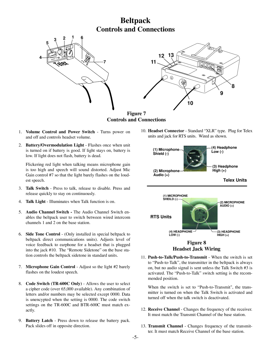
Figure 7
Controls and Connections
1. | Volume Control and Power Switch - Turns power on |
| and off and controls headset volume. |
2. | Battery/Overmodulation Light - Flashes once when unit |
10. Headset Connector - Standard “XLR” type. Plug for Telex units and jack for RTS units. Wired as shown.
is turned on if battery is good. If light stays on, battery is |
(1) Microphone
(4) Headphone
low. If light does not flash, battery is dead. |
Flickering red light when talking means microphone gain |
Shield
Low
(3) Headphone
| is too high and speech will sound distorted. Adjust Mic |
| Gain control #7 so that the light barely flashes on the loud- |
| est speech. |
3. | Talk Switch - Press to talk, release to disable. Press and |
| release quickly to stay on continuously. |
4. | Talk Light - Illuminates when Talk function is on. |
5. | Audio Channel Switch - The Audio Channel Switch en- |
| ables the beltpack user to switch between wired intercom |
| channels 1 and 2 on the base station. |
6. | Side Tone Control - (Only installed in special beltpack to |
| beltpack direct communications units). Adjusts level of |
| voice feedback to earphone for a headset that is plugged |
| into the jack #10. The “Remote Sidetone” on the base sta- |
| tion controls the beltpack sidetone in standard units. |
7. | Microphone Gain Control - Adjust so the light #2 barely |
| flashes on the loudest speech. |
8. | Code Switch |
| a cipher code (over 65,000 available). Any combination of |
| letters and/or numbers may be selected except 0000. Data |
| is unencypted when the setting is 0000. The code switch |
| settings on the |
| actly. |
9. | Battery Latch - Press down to release the battery pack. |
| Pack slides off in opposite direction. |
(2) MicrophoneHigh (+)
Audio (+)
Telex Units
(1)MICROPHONE SHEILD
(2) MICROPHONE AUDIO (+)
RTS Units
(4) HEADPHONE | (3) HEADPHONE |
LOW | HIGH (+) |
Figure 8
Headset Jack Wiring
11.
When the switch is set to
12.Receive Channel - Changes the frequency of the receiver. It must match the Transmit Channel of the base station.
13.Transmit Channel - Changes frequency of the transmit- ter. It must match Receive Channel of the base station.