Tech Tips
Codes Settings and the BTR600C
While the BTR-600C and corresponding TR-600C have over 65,000 different codes that may be se- lected by the user, there are actually over 16 million different codes in the units. The microprocessor in each base station and corresponding beltpack has two unique numbers programmed into them from the factory. The external four code switch settings are used in conjunction with these two internal, non-accessible, numbers to encrypt and decrypt au- dio sent to and from the units.
Frequency Interaction
Unfortunately, radio frequency (RF) channels can- not be randomly selected for use in radio devices. They must be selected to avoid known frequencies in use, FCC restrictions on the location of devices, and even interference between your own RF de- vices. The channels selected by Telex for Radiocom systems are chosen to minimum possible interfer- ence. This is why it is always important to inform Telex about frequencies of other Radiocom or other RF devices that will be used with any additional Radiocom equipment ordered.
Microphone Gain Adjustment
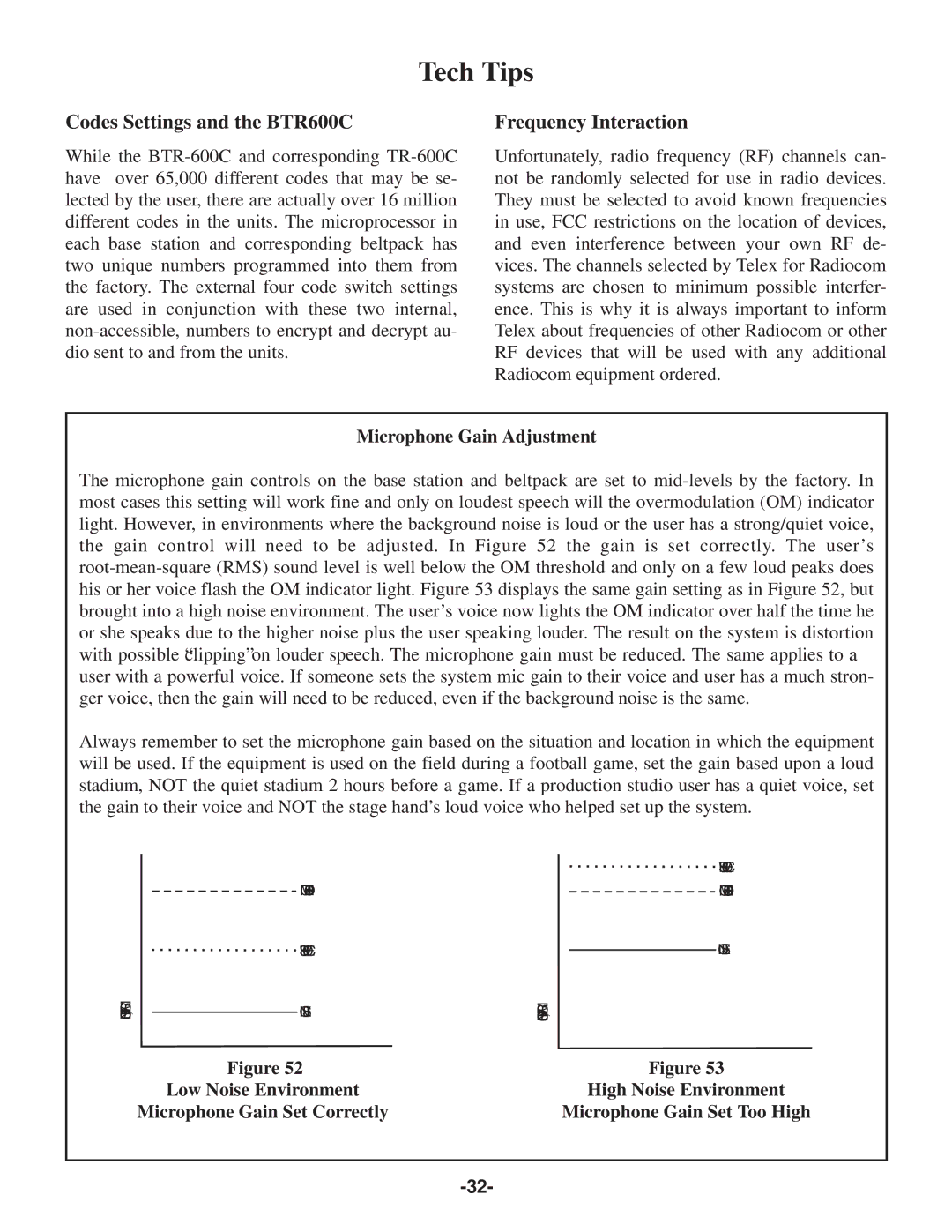
The microphone gain controls on the base station and beltpack are set to mid-levels by the factory. In most cases this setting will work fine and only on loudest speech will the overmodulation (OM) indicator light. However, in environments where the background noise is loud or the user has a strong/quiet voice, the gain control will need to be adjusted. In Figure 52 the gain is set correctly. The user’s root-mean-square (RMS) sound level is well below the OM threshold and only on a few loud peaks does his or her voice flash the OM indicator light. Figure 53 displays the same gain setting as in Figure 52, but brought into a high noise environment. The user’s voice now lights the OM indicator over half the time he or she speaks due to the higher noise plus the user speaking louder. The result on the system is distortion with possible “clipping” on louder speech. The microphone gain must be reduced. The same applies to a user with a powerful voice. If someone sets the system mic gain to their voice and user has a much stron- ger voice, then the gain will need to be reduced, even if the background noise is the same.
Always remember to set the microphone gain based on the situation and location in which the equipment will be used. If the equipment is used on the field during a football game, set the gain based upon a loud stadium, NOT the quiet stadium 2 hours before a game. If a production studio user has a quiet voice, set the gain to their voice and NOT the stage hand’s loud voice who helped set up the system.
RMS | OM THRESHOLD |
SOUNDLEVEL, | NOISE |
| USER'S VOICE |
Figure 52
Low Noise Environment
Microphone Gain Set Correctly
RMS | | USER'S VOICE |
| OM THRESHOLD |
LEVEL,SOUND | |
| NOISE |
| |
Figure 53
High Noise Environment
Microphone Gain Set Too High