| ON |
6 | T O I C |
S | X |
| AU |
| OF F |
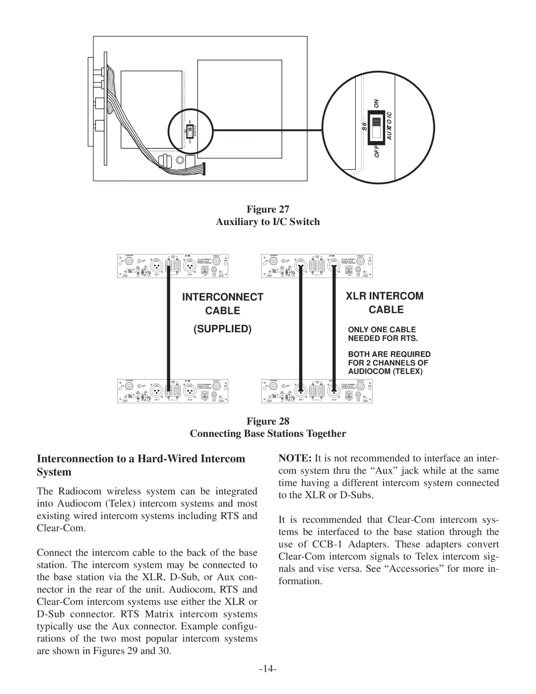
Figure 27
Auxiliary to I/C Switch
ON
S 6
OF F
AU X T O I C
TRANSMIT
ANT. |
| AUDIO | PUSH |
| OUT |
| |
| XMIT | DUAL |
|
I /C | MODE | LISTEN |
|
TELEX | RTS REMOTE | CH2 + 2 |
|
A | O | O |
|
| F | N |
|
B | F |
| I/C 1 |
TRANSMIT |
| CH2 + 1 | |
CHANNEL | CONT. | LEVEL |
|
TRANSMIT
ANT. |
| AUDIO | PUSH |
| OUT |
| |
| XMIT | DUAL |
|
I /C | MODE | LISTEN |
|
TELEX | RTS REMOTE | CH2 + 2 |
|
A | O | O |
|
| F | N |
|
B | F |
| I/C 1 |
TRANSMIT |
| CH2 + 1 | |
CHANNEL | CONT. | LEVEL |
|
LOOP |
|
| RECEIVE | TRANSMIT |
|
|
| LOOP | ||
THRU |
|
|
|
|
|
|
|
| THRU |
|
| PUSH | FCC ID. B5DM503 |
| ANT. | ANT. |
| AUDIO | PUSH |
| PUSH |
|
| MADE IN U.S.A. |
|
| OUT |
|
|
| ||
|
| PATENT PENDING |
|
|
|
|
|
|
|
|
|
|
|
|
|
| XMIT | DUAL |
|
|
|
|
|
|
|
| I /C | MODE | LISTEN |
|
|
|
|
|
|
|
| TELEX RTS | REMOTE | CH2 + 2 |
|
|
|
|
|
|
| A | A | O | O |
|
|
|
|
|
|
|
|
| F | N |
|
|
|
| I/C 2 |
| POWER | B | B | F |
| I/C 1 |
| I/C 2 |
I/C | AUX | RECEIVE | TRANSMIT |
| CH2 + 1 | I/C | ||||
|
|
| AC/DC | CHANNEL | CHANNEL | CONT. | LEVEL |
|
|
|
INTERCONNECT
CABLE
(SUPPLIED)
LOOP |
| RECEIVE | TRANSMIT |
|
|
| LOOP | |||
THRU |
|
|
|
|
|
|
|
| THRU |
|
| PUSH | FCC ID. B5DM503 |
| ANT. | ANT. |
| AUDIO | PUSH |
| PUSH |
|
| MADE IN U.S.A. |
|
| OUT |
|
|
| ||
|
| PATENT PENDING |
|
|
|
|
|
|
|
|
|
|
|
|
|
| XMIT | DUAL |
|
|
|
|
|
|
|
| I /C | MODE | LISTEN |
|
|
|
|
|
|
|
| TELEX RTS | REMOTE | CH2 + 2 |
|
|
|
|
|
|
| A | A | O | O |
|
|
|
|
|
|
|
|
| F | N |
|
|
|
| I/C 2 |
| POWER | B | B | F |
| I/C 1 |
| I/C 2 |
I/C | AUX | RECEIVE | TRANSMIT |
| CH2 + 1 | I/C | ||||
|
|
| AC/DC | CHANNEL | CHANNEL | CONT. | LEVEL |
|
|
|
RECEIVE
FCC ID. B5DM503
MADE IN U.S.A.ANT.
PATENT PENDING
|
| A |
| POWER | B |
AUX | RECEIVE | |
| AC/DC | CHANNEL |
XLR INTERCOM
CABLE
ONLY ONE CABLE NEEDED FOR RTS.
BOTH ARE REQUIRED FOR 2 CHANNELS OF AUDIOCOM (TELEX)
RECEIVE
FCC ID. B5DM503
MADE IN U.S.A.ANT.
PATENT PENDING
|
| A |
| POWER | B |
AUX | RECEIVE | |
| AC/DC | CHANNEL |
Figure 28
Connecting Base Stations Together
Interconnection to a Hard-Wired Intercom System
The Radiocom wireless system can be integrated into Audiocom (Telex) intercom systems and most existing wired intercom systems including RTS and
Connect the intercom cable to the back of the base station. The intercom system may be connected to the base station via the XLR,
NOTE: It is not recommended to interface an inter- com system thru the “Aux” jack while at the same time having a different intercom system connected to the XLR or
It is recommended that
