Wall Mount Installation
Note: see below if cabinet installation is preferred
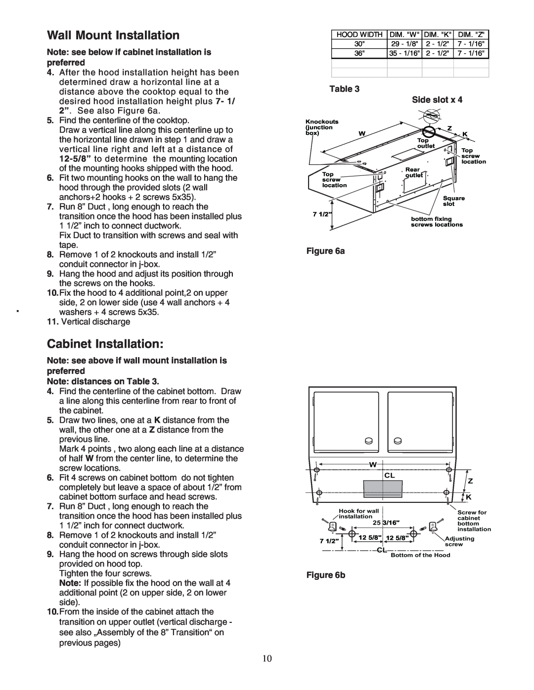
4.After the hood installation height has been determined draw a horizontal line at a distance above the cooktop equal to the desired hood installation height plus 7- 1/ 2”. See also Figure 6a.
5.Find the centerline of the cooktop.
Draw a vertical line along this centerline up to the horizontal line drawn in step 1 and draw a vertical line right and left at a distance of
6.Fit two mounting hooks on the wall to hang the hood through the provided slots (2 wall anchors+2 hooks + 2 screws 5x35).
7.Run 8” Duct , long enough to reach the transition once the hood has been installed plus 1 1/2” inch to connect ductwork.
Fix Duct to transition with screws and seal with tape.
8.Remove 1 of 2 knockouts and install 1/2” conduit connector in
9.Hang the hood and adjust its position through the screws on the hooks.
10.Fix the hood to 4 additional point,2 on upper side, 2 on lower side (use 4 wall anchors + 4 washers + 4 screws 5x35.
11.Vertical discharge
Cabinet Installation:
Note: see above if wall mount installation is preferred
Note: distances on Table 3.
4.Find the centerline of the cabinet bottom. Draw a line along this centerline from rear to front of the cabinet.
5.Draw two lines, one at a K distance from the wall, the other one at a Z distance from the previous line.
Mark 4 points , two along each line at a distance of half W from the center line, to determine the screw locations.
6.Fit 4 screws on cabinet bottom do not tighten completely but leave a space of about 1/2” from cabinet bottom surface and head screws.
7.Run 8” Duct , long enough to reach the transition once the hood has been installed plus 1 1/2” inch for connect ductwork.
8.Remove 1 of 2 knockouts and install 1/2” conduit connector in
9.Hang the hood on screws through side slots provided on hood top.
Tighten the four screws.
Note: If possible fix the hood on the wall at 4 additional point (2 on upper side, 2 on lower
side).
10.From the inside of the cabinet attach the transition on upper outlet (vertical discharge - see also „Assembly of the 8” Transition“ on previous pages)
HOOD WIDTH | DIM. "W" | DIM. "K" | DIM. "Z" |
30" | 29 - 1/8" | 2 - 1/2" | 7 - 1/16" |
36" | 35 - 1/16" | 2 - 1/2" | 7 - 1/16" |
|
|
|
|
|
|
|
|
Table 3
|
| Side slot x 4 | |
Knockouts |
|
| Z |
(junction |
|
| |
box) | W | Top | K |
|
|
| |
|
| outlet | Top |
|
|
| |
|
|
| screw |
|
|
| location |
Top |
| Rear |
|
| outlet |
| |
screw |
|
|
|
location |
|
|
|
|
|
| Square |
|
|
| slot |
7 1/2" |
| bottom fixing | |
|
| ||
|
| screws locations | |
Figure 6a
W
CL | Z |
| |
| K |
| Hook for wall |
| Screw for |
| installation |
| cabinet |
| 25 3/16" | bottom | |
|
|
| installation |
7 1/2" | 12 5/8" | 12 5/8" | Adjusting |
|
| screw | |
|
|
| |
| CL Bottom of the Hood | ||
Figure 6b
10