All installations and services must be performed by qualified service personnel.
Horizontal runs of air intake pipe shall slope downward at least ¼ inch per foot from the outlet of the last elbow or last horizontal run, before exiting the wall, to the intake termination beyond the outside wall. This slope will permit proper drainage of any precipitation that enters the intake pipe.
6.The exhaust vent pipe shall be supported at every joint (no more than
7.The maximum permissible length of piping (consisting of a combination of straight pipe and a corresponding number of elbows) permitted is:
•75 equivalent feet, for the exhaust vent system, and
•70 equivalent feet, for the combustion air intake system.
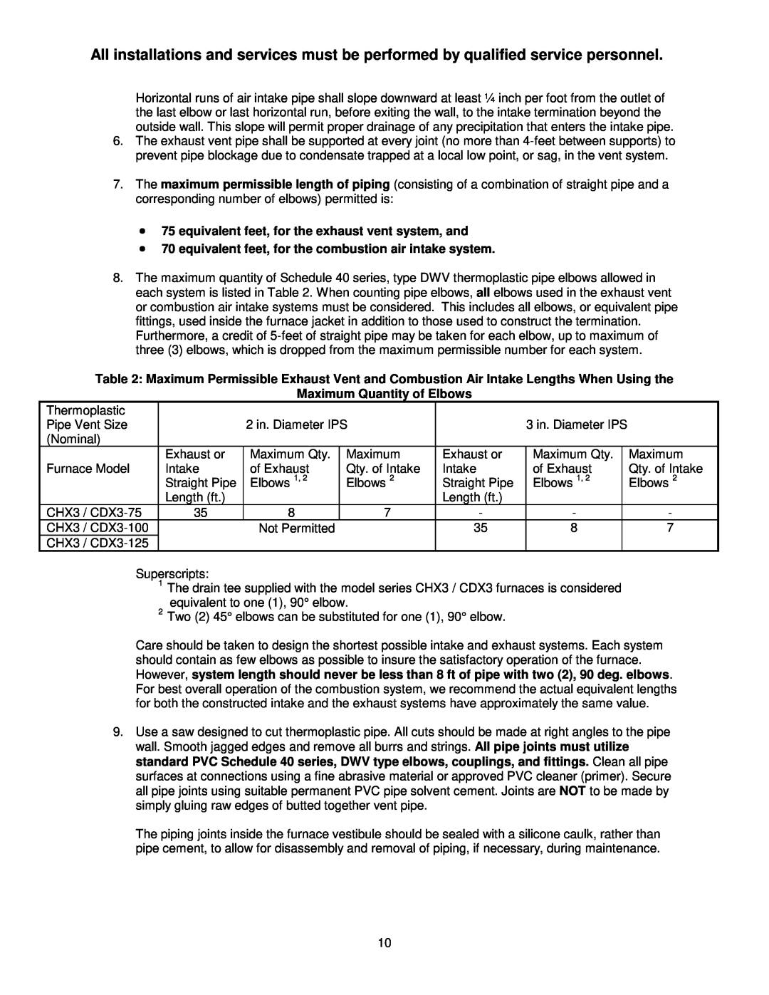
8.The maximum quantity of Schedule 40 series, type DWV thermoplastic pipe elbows allowed in each system is listed in Table 2. When counting pipe elbows, all elbows used in the exhaust vent or combustion air intake systems must be considered. This includes all elbows, or equivalent pipe fittings, used inside the furnace jacket in addition to those used to construct the termination. Furthermore, a credit of
Table 2: Maximum Permissible Exhaust Vent and Combustion Air Intake Lengths When Using the
Maximum Quantity of Elbows
Thermoplastic |
|
|
|
|
|
|
|
Pipe Vent Size |
| 2 in. Diameter IPS |
| 3 in. Diameter IPS |
| ||
(Nominal) |
|
|
|
|
|
|
|
| Exhaust or | Maximum Qty. | Maximum | Exhaust or | Maximum Qty. |
| Maximum |
Furnace Model | Intake | of Exhaust | Qty. of Intake | Intake | of Exhaust |
| Qty. of Intake |
| Straight Pipe | Elbows 1, 2 | Elbows 2 | Straight Pipe | Elbows 1, 2 |
| Elbows 2 |
| Length (ft.) |
|
| Length (ft.) |
|
|
|
CHX3 / | 35 | 8 | 7 | - | - |
| - |
CHX3 / |
| Not Permitted |
| 35 | 8 |
| 7 |
CHX3 / |
|
|
|
|
|
|
|
Superscripts:
1The drain tee supplied with the model series CHX3 / CDX3 furnaces is considered equivalent to one (1), 90° elbow.
2Two (2) 45° elbows can be substituted for one (1), 90° elbow.
Care should be taken to design the shortest possible intake and exhaust systems. Each system should contain as few elbows as possible to insure the satisfactory operation of the furnace. However, system length should never be less than 8 ft of pipe with two (2), 90 deg. elbows. For best overall operation of the combustion system, we recommend the actual equivalent lengths for both the constructed intake and the exhaust systems have approximately the same value.
9.Use a saw designed to cut thermoplastic pipe. All cuts should be made at right angles to the pipe wall. Smooth jagged edges and remove all burrs and strings. All pipe joints must utilize standard PVC Schedule 40 series, DWV type elbows, couplings, and fittings. Clean all pipe surfaces at connections using a fine abrasive material or approved PVC cleaner (primer). Secure all pipe joints using suitable permanent PVC pipe solvent cement. Joints are NOT to be made by simply gluing raw edges of butted together vent pipe.
The piping joints inside the furnace vestibule should be sealed with a silicone caulk, rather than pipe cement, to allow for disassembly and removal of piping, if necessary, during maintenance.
10