Thermo Products CDX3-125N, CDX3-75N, CHX3-75N, CHX3-125N, CHX3-100N, CDX3-100N operation manual A

Models: CDX3-100N CHX3-100N CDX3-125N CHX3-125N CHX3-75N CDX3-75N

1 65
Download 65 pages 33.09 Kb
Page 33
Image 33
Figure 18A

All installations and services must be performed by qualified service personnel.
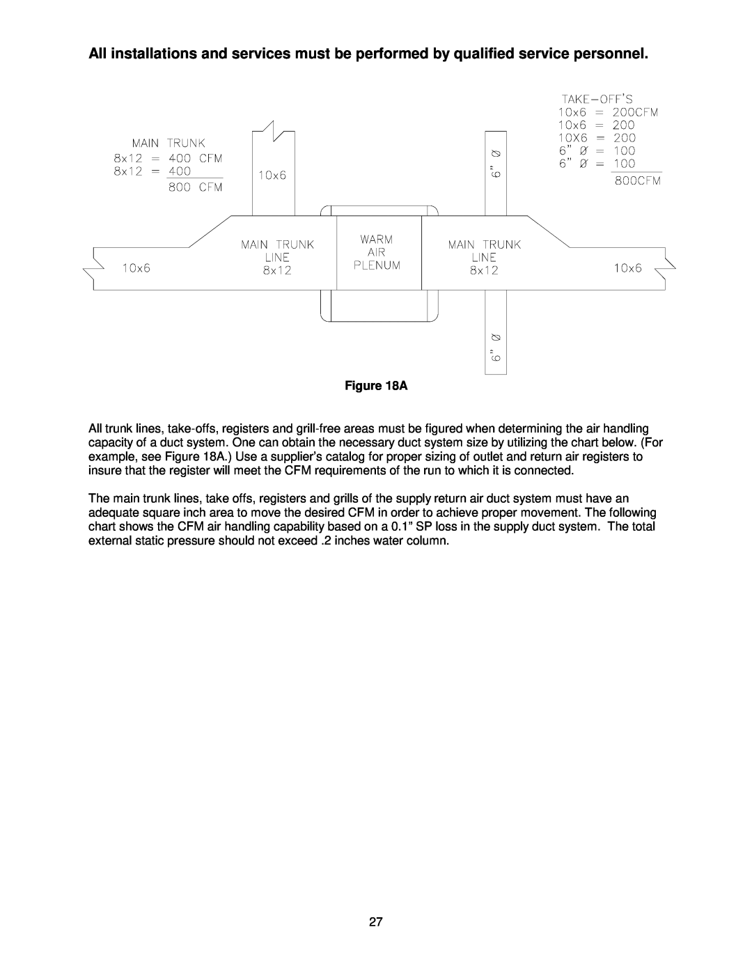
Figure 18A

All trunk lines, take-offs, registers and grill-free areas must be figured when determining the air handling capacity of a duct system. One can obtain the necessary duct system size by utilizing the chart below. (For example, see Figure 18A.) Use a supplier’s catalog for proper sizing of outlet and return air registers to insure that the register will meet the CFM requirements of the run to which it is connected.

The main trunk lines, take offs, registers and grills of the supply return air duct system must have an adequate square inch area to move the desired CFM in order to achieve proper movement. The following chart shows the CFM air handling capability based on a 0.1” SP loss in the supply duct system. The total external static pressure should not exceed .2 inches water column.

27

Page 33
Image 33
Thermo Products CDX3-125N, CDX3-75N, CHX3-75N, CHX3-125N, CHX3-100N, CDX3-100N operation manual A