All installations and services must be performed by qualified service personnel.
NOTE: The hose, when moved, must be shortened (cut) to ensure that no excess hose exists to cause a sag, loop, or "water trap".
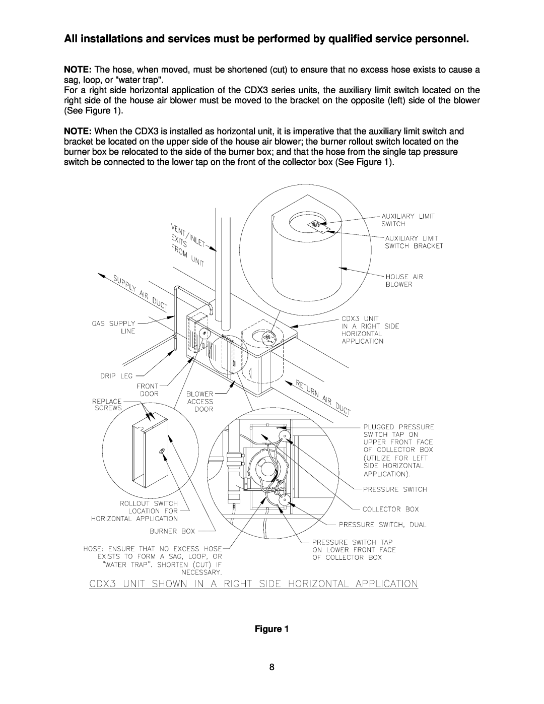
For a right side horizontal application of the CDX3 series units, the auxiliary limit switch located on the right side of the house air blower must be moved to the bracket on the opposite (left) side of the blower (See Figure 1).
NOTE: When the CDX3 is installed as horizontal unit, it is imperative that the auxiliary limit switch and bracket be located on the upper side of the house air blower; the burner rollout switch located on the burner box be relocated to the side of the burner box; and that the hose from the single tap pressure switch be connected to the lower tap on the front of the collector box (See Figure 1).
Figure 1
8