All installations and services must be performed by qualified service personnel.
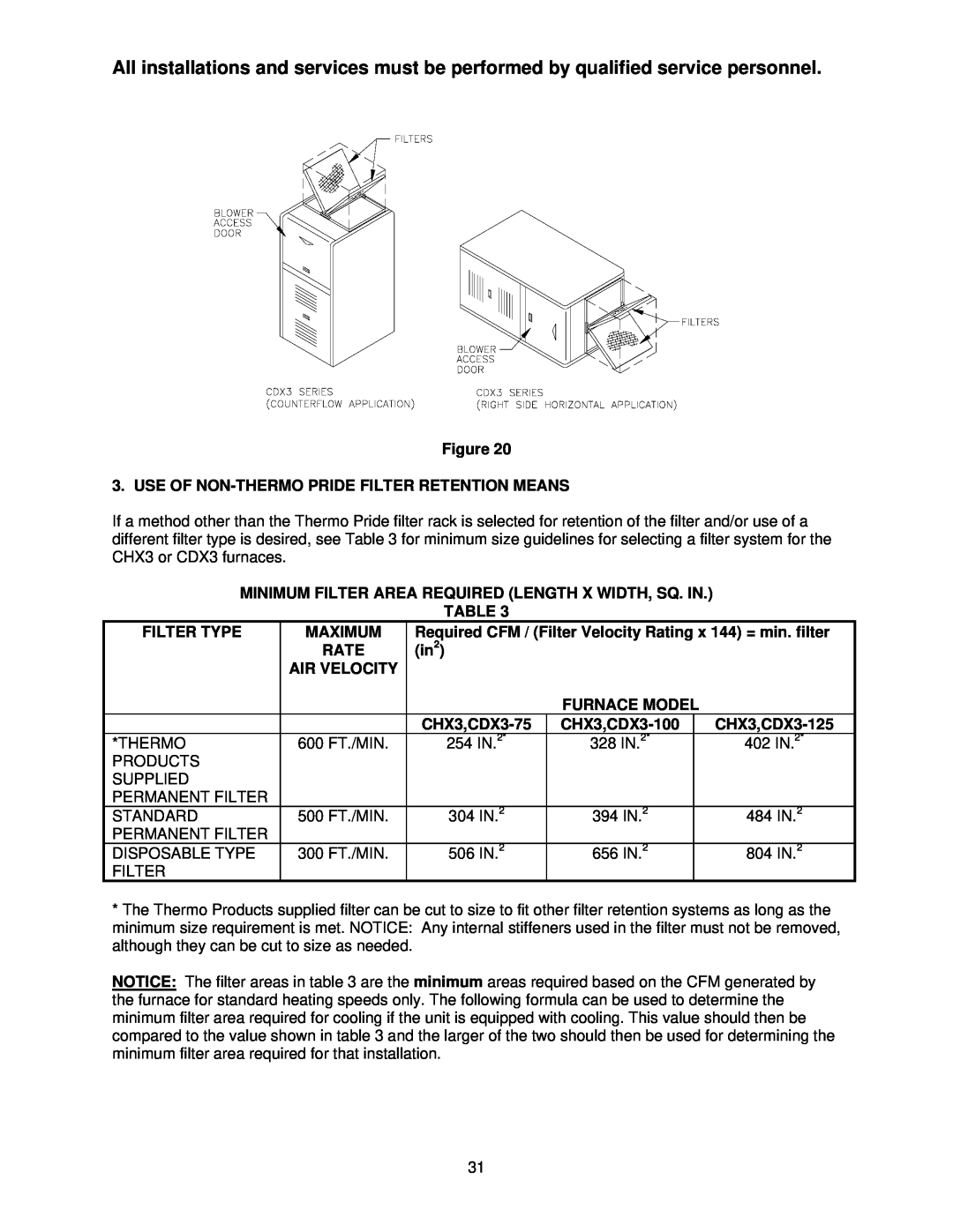
Figure 20
3. USE OF
If a method other than the Thermo Pride filter rack is selected for retention of the filter and/or use of a different filter type is desired, see Table 3 for minimum size guidelines for selecting a filter system for the CHX3 or CDX3 furnaces.
MINIMUM FILTER AREA REQUIRED (LENGTH X WIDTH, SQ. IN.)
TABLE 3
FILTER TYPE | MAXIMUM | Required CFM / (Filter Velocity Rating x 144) = min. filter | |||
| RATE | (in2) |
|
|
|
| AIR VELOCITY |
|
|
|
|
|
|
| FURNACE MODEL |
| |
|
|
| |||
*THERMO | 600 FT./MIN. | 254 IN.2* | 328 IN.2* |
| 402 IN.2* |
PRODUCTS |
|
|
|
|
|
SUPPLIED |
|
|
|
|
|
PERMANENT FILTER |
|
|
|
|
|
STANDARD | 500 FT./MIN. | 304 IN.2 | 394 IN.2 |
| 484 IN.2 |
PERMANENT FILTER |
|
|
|
|
|
DISPOSABLE TYPE | 300 FT./MIN. | 506 IN.2 | 656 IN.2 |
| 804 IN.2 |
FILTER |
|
|
|
|
|
*The Thermo Products supplied filter can be cut to size to fit other filter retention systems as long as the minimum size requirement is met. NOTICE: Any internal stiffeners used in the filter must not be removed, although they can be cut to size as needed.
NOTICE: The filter areas in table 3 are the minimum areas required based on the CFM generated by the furnace for standard heating speeds only. The following formula can be used to determine the minimum filter area required for cooling if the unit is equipped with cooling. This value should then be compared to the value shown in table 3 and the larger of the two should then be used for determining the minimum filter area required for that installation.
31