SECTION VI: EVACUATION
It will be necessary to evacuate the system to 500 microns or less. If a leak is suspected, leak test with dry nitrogen to locate the leak. Repair the leak and test again.
To verify that the system has no leaks, simply close the valve to the vac- uum pump suction to isolate the pump and hold the system under vac- uum. Watch the micron gauge for a few minutes. If the micron gauge indicates a steady and continuous rise, it’s an indication of a leak. If the gauge shows a rise, then levels off after a few minutes and remains fairly constant, its an indication that the system is leak free but still con- tains moisture and may require further evacuation if the reading is above 500 microns.
SECTION VII: SYSTEM CHARGE
To ensure that your unit performs at the published levels, it is important that the indoor airflow is determined and refrigerant charge added accordingly.
Measure Indoor Air Flow:
To determine rated air flow for a specific match, consult the technical lit- erature at www.upgnet.com.
Examples:
GHGD18S41S2 + AHE18B3XH21 = 610 CFM THGF24S41S1+ FC35B3XN1 = 800 CFM THJR36S41S4 + AHV36C3XH21 = 940 CFM
YHJD48S44S3 + FC60C3XN1H + TM9X100C20MP11A = 1625 CFM. THGF60S41S1 + MC62D3XH1 + MV20DN21C = 1855 CFM(High) & 1160 (Low)
When attempting to match this air flow, select the lowest possible speed tap and measure the actual flow and adjust as necessary. Checking jumper pin setting tables is not an acceptable method for determining air flow. To determine indoor air flow, first measure the static pressure with a manometer between the filter and blower. On a
Charging the Unit:
The factory charge in the outdoor unit includes enough charge for the unit, a 15 ft. (4.6 m) line set, and the smallest indoor coil/air handler
The "TOTAL SYSTEM CHARGE" must be permanently marked on the unit data plate.
Do not leave the system open to the atmosphere.
Total system charge is determined as follows:
1.Determine outdoor unit factory charge from Tabular Data Sheet.
2.Determine indoor coil adjustment (if any) from Tabular Data Sheet.
3.Calculate the additional charge for lineset using the Tabular Data Sheet if line length is greater than 15 feet (4.6 m).
4.Total system charge = item 1 + item 2 + item 3.
5.Permanently mark the unit data plate with the total amount of refrig- erant in the system.
NOTICE
This method is for systems that only have interconnecting lines. If any other objects that adjust the charge levels are placed between the indoor and outdoor units (example: a refrigerant flow meter), then before adding charge, the device must first be removed. Follow the steps above. Run the system in both cooling and heating mode and record the high side pressure in each mode. Then insert the device and charge the system by matching the same high side pressure in both heating and cooling as that value recorded without the device. It is not acceptable to add a
DO NOT attempt to pump “Total System Charge” into outdoor unit for maintenance, service, etc. This may cause damage to the compres- sor and/or other components. The outdoor unit only has enough vol- ume for the factory charge, not the “Total System Charge”.
Using the charging charts:
The unit includes heating charging charts and cooling charging charts. All units include a subcooling charging chart for cooling. If the unit can be used with an indoor orifice, then a cooling superheat chart is also included. If a charging chart is not on the unit, then it can be obtained at www.upgnet.com.
These charts should not be used to charge the unit. They are refer- ence charts for servicing the unit. After the unit has been serviced, collect the charge and weigh it back in according to the directions.
Charging by only one method (cooling or heating), as well as charging to a superheating or subcooling value is not acceptable. Most heat pumps are sensitive to charge in one mode, so charging by only one mode can cause it under perform in the other.
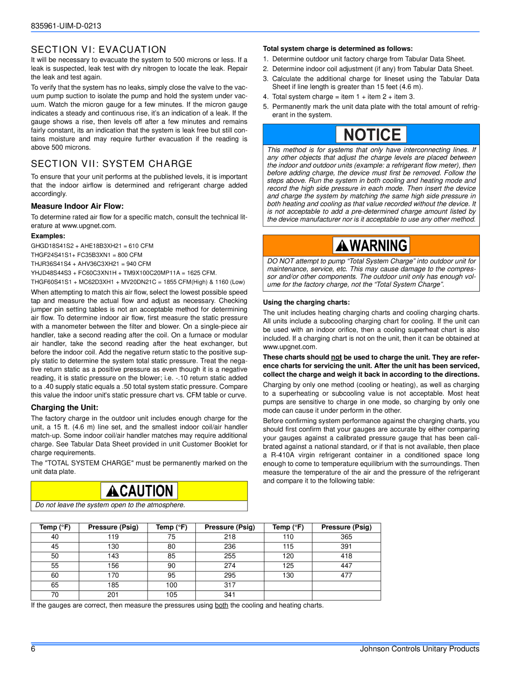
Before confirming system performance against the charging charts, you should first confirm that your gauges are accurate by either comparing your gauges against a calibrated pressure gauge that has been cali- brated against a national standard, or if that is not available, then place a
Temp (°F) | Pressure (Psig) | Temp (°F) | Pressure (Psig) | Temp (°F) | Pressure (Psig) |
40 | 119 | 75 | 218 | 110 | 365 |
45 | 130 | 80 | 236 | 115 | 391 |
50 | 143 | 85 | 255 | 120 | 418 |
55 | 156 | 90 | 274 | 125 | 447 |
60 | 170 | 95 | 295 | 130 | 477 |
65 | 185 | 100 | 317 |
|
|
70 | 201 | 105 | 341 |
|
|
If the gauges are correct, then measure the pressures using both the cooling and heating charts.
6 | Johnson Controls Unitary Products |