|
|
|
|
|
|
| ||
| RUN TIME |
| TEST |
|
|
|
|
|
XL | 90 30 | TEST |
|
|
| RUNTIME 90 60 30 | MIN. SEL | |
XL |
|
|
| Test | ||||
|
|
|
| |||||
R |
|
|
|
| ||||
| RUN TIME |
|
|
|
|
|
|
|
R |
|
|
|
|
|
|
|
|
C |
|
|
|
|
|
|
|
|
C |
|
|
|
|
| ALTERNATE |
| |
Y |
|
|
|
|
|
| ||
Y |
|
|
|
|
| CONFIGURATION | ||
|
|
|
|
|
|
|
| |
O |
|
|
|
|
|
|
|
|
O |
|
|
|
|
|
|
|
|
W |
|
|
|
|
|
|
|
|
W |
|
|
|
|
|
|
|
|
W1/66 |
|
|
|
|
|
|
|
|
W1/66 |
|
|
|
|
|
|
|
|
R3 |
|
|
|
|
|
|
|
|
K2 | K1 |
| K3 | COND. | FAN |
|
| |
|
|
|
|
|
|
| ||
REV | PRESSURE |
| DFST | M |
|
|
|
|
VALVE | SWITCH |
| T’STAT | M |
|
|
|
|
REV | PRESSURE | COMP RLY |
| DFST |
|
|
| |
OM |
|
|
|
|
| ALTERNATE |
| |
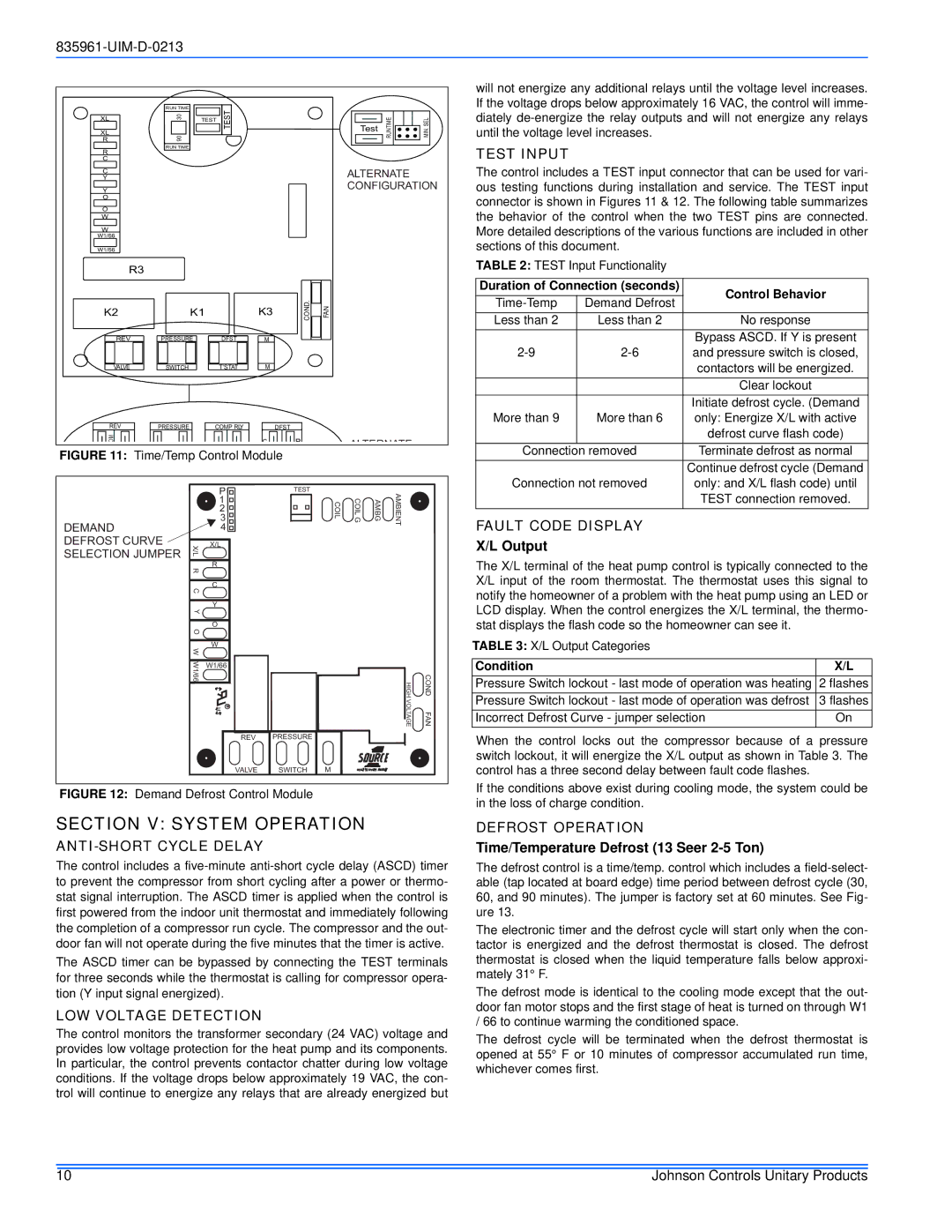
FIGURE 11: Time/Temp Control Module
will not energize any additional relays until the voltage level increases. If the voltage drops below approximately 16 VAC, the control will imme- diately de-energize the relay outputs and will not energize any relays until the voltage level increases.
TEST INPUT
The control includes a TEST input connector that can be used for vari- ous testing functions during installation and service. The TEST input connector is shown in Figures 11 & 12. The following table summarizes the behavior of the control when the two TEST pins are connected. More detailed descriptions of the various functions are included in other sections of this document.
TABLE 2: TEST Input Functionality
Duration of Connection (seconds) | Control Behavior | ||
| Demand Defrost | ||
| |||
Less than 2 | Less than 2 | No response | |
|
| Bypass ASCD. If Y is present | |
and pressure switch is closed, | |||
|
| contactors will be energized. | |
|
| Clear lockout | |
|
| Initiate defrost cycle. (Demand | |
More than 9 | More than 6 | only: Energize X/L with active | |
|
| defrost curve flash code) | |
Connection | removed | Terminate defrost as normal | |
|
| Continue defrost cycle (Demand | |
Connection not removed | only: and X/L flash code) until | ||
DEMAND DEFROST CURVE SELECTION JUMPER
X/L R C Y O W W1/66
PTEST
1
2
3 ![]()
4 ![]()
X/L
R
C
Y
O
W
W1/66
REV PRESSURE
COIL | COIL G | AMBG | AMBIENT |
HIGH | COND |
VOLTAGE | FAN |
TEST connection removed. |
FAULT CODE DISPLAY
X/L Output
The X/L terminal of the heat pump control is typically connected to the X/L input of the room thermostat. The thermostat uses this signal to notify the homeowner of a problem with the heat pump using an LED or LCD display. When the control energizes the X/L terminal, the thermo- stat displays the flash code so the homeowner can see it.
TABLE 3: X/L Output Categories |
|
|
|
Condition | X/L |
Pressure Switch lockout - last mode of operation was heating | 2 flashes |
Pressure Switch lockout - last mode of operation was defrost | 3 flashes |
Incorrect Defrost Curve - jumper selection | On |
When the control locks out the compressor because of a pressure switch lockout, it will energize the X/L output as shown in Table 3. The
VALVE SWITCH M
FIGURE 12: Demand Defrost Control Module
SECTION V: SYSTEM OPERATION
ANTI-SHORT CYCLE DELAY
The control includes a
The ASCD timer can be bypassed by connecting the TEST terminals for three seconds while the thermostat is calling for compressor opera- tion (Y input signal energized).
LOW VOLTAGE DETECTION
The control monitors the transformer secondary (24 VAC) voltage and provides low voltage protection for the heat pump and its components. In particular, the control prevents contactor chatter during low voltage conditions. If the voltage drops below approximately 19 VAC, the con- trol will continue to energize any relays that are already energized but
control has a three second delay between fault code flashes.
If the conditions above exist during cooling mode, the system could be in the loss of charge condition.
DEFROST OPERATION
Time/Temperature Defrost (13 Seer 2-5 Ton)
The defrost control is a time/temp. control which includes a
The electronic timer and the defrost cycle will start only when the con- tactor is energized and the defrost thermostat is closed. The defrost thermostat is closed when the liquid temperature falls below approxi- mately 31° F.
The defrost mode is identical to the cooling mode except that the out- door fan motor stops and the first stage of heat is turned on through W1 / 66 to continue warming the conditioned space.
The defrost cycle will be terminated when the defrost thermostat is opened at 55° F or 10 minutes of compressor accumulated run time, whichever comes first.
10 | Johnson Controls Unitary Products |