|
|
|
|
|
|
| A To circuit breakers | |
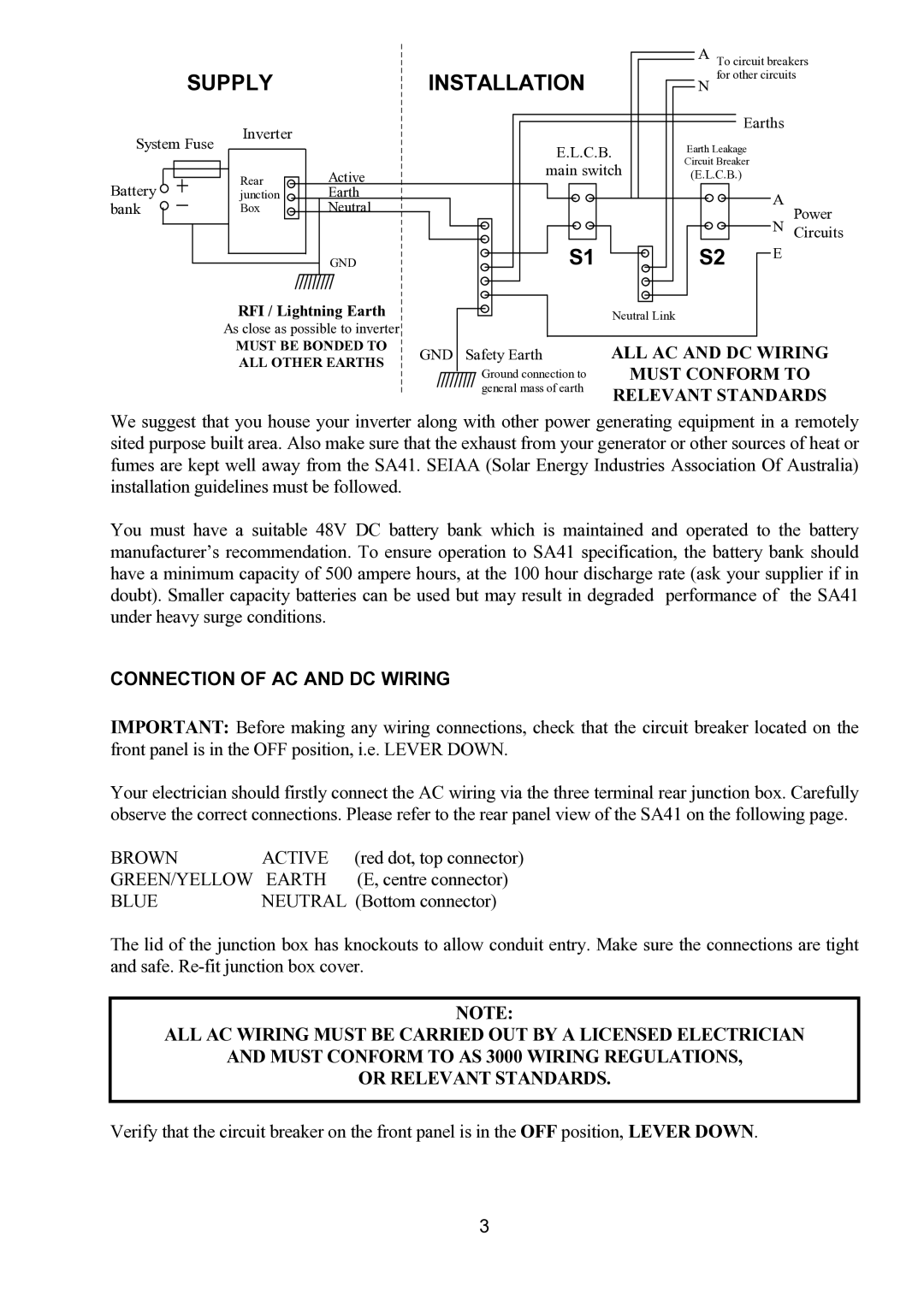
| SUPPLY |
| INSTALLATION |
| N for other circuits | |||
|
| Inverter |
|
|
|
| Earths | |
System Fuse |
|
| E.L.C.B. |
| Earth Leakage |
| ||
|
|
|
|
| ||||
|
|
|
|
|
|
| ||
|
|
|
|
| main switch | Circuit Breaker |
| |
|
| Rear | Active |
| (E.L.C.B.) |
| ||
Battery |
|
|
|
|
| |||
| junction | Earth |
|
|
|
| A | |
bank |
| Box | Neutral |
|
|
|
| |
|
|
|
|
| Power | |||
|
|
|
|
|
|
|
| N Circuits |
|
|
| GND |
| S1 |
| S2 | E |
|
| RFI / Lightning Earth |
|
| Neutral Link |
| ||
|
| As close as possible to inverter |
|
|
|
|
| |
|
| MUST BE BONDED TO | GND | Safety Earth | ALL AC AND DC WIRING | |||
|
| ALL OTHER EARTHS | ||||||
|
|
| Ground connection to |
| MUST CONFORM TO | |||
|
|
|
|
|
| |||
|
|
|
|
| general mass of earth | RELEVANT STANDARDS | ||
|
|
|
|
|
| |||
We suggest that you house your inverter along with other power generating equipment in a remotely sited purpose built area. Also make sure that the exhaust from your generator or other sources of heat or fumes are kept well away from the SA41. SEIAA (Solar Energy Industries Association Of Australia) installation guidelines must be followed.
You must have a suitable 48V DC battery bank which is maintained and operated to the battery manufacturer’s recommendation. To ensure operation to SA41 specification, the battery bank should have a minimum capacity of 500 ampere hours, at the 100 hour discharge rate (ask your supplier if in doubt). Smaller capacity batteries can be used but may result in degraded performance of the SA41 under heavy surge conditions.
CONNECTION OF AC AND DC WIRING
IMPORTANT: Before making any wiring connections, check that the circuit breaker located on the front panel is in the OFF position, i.e. LEVER DOWN.
Your electrician should firstly connect the AC wiring via the three terminal rear junction box. Carefully observe the correct connections. Please refer to the rear panel view of the SA41 on the following page.
BROWN | ACTIVE | (red dot, top connector) |
GREEN/YELLOW | EARTH | (E, centre connector) |
BLUE | NEUTRAL (Bottom connector) | |
The lid of the junction box has knockouts to allow conduit entry. Make sure the connections are tight and safe.
NOTE:
ALL AC WIRING MUST BE CARRIED OUT BY A LICENSED ELECTRICIAN
AND MUST CONFORM TO AS 3000 WIRING REGULATIONS,
OR RELEVANT STANDARDS.
Verify that the circuit breaker on the front panel is in the OFF position, LEVER DOWN.
3