5. Computer and Alarm Connections
At the rear of the UPS is an interface that allows direct communication with a computer system (see figure 2). There is a RS232 serial data interface, a USB data interface, and an emergency power off switch. The RS232 port and the USB interface cannot be used simultaneously.
In addition there is an optional interface slot that allows for the installation of communications cards. It may be used in parallel with either the RS232 or USB ports. An SNMP/WEB card is available for the optional interface slot that allows for the RemotEye II to manage and monitor the system over a network or over the internet.
5.1RS-232 Standard Interface Port
Only the communication cable provided with the UPS may be used to connect the UPS to a computer when using the RS232 port of the UPS. Ensure that the operating system of the computer supports RS232 communications. Other advanced power protection solutions, such as SNMP, are available from your dealer.
The
|
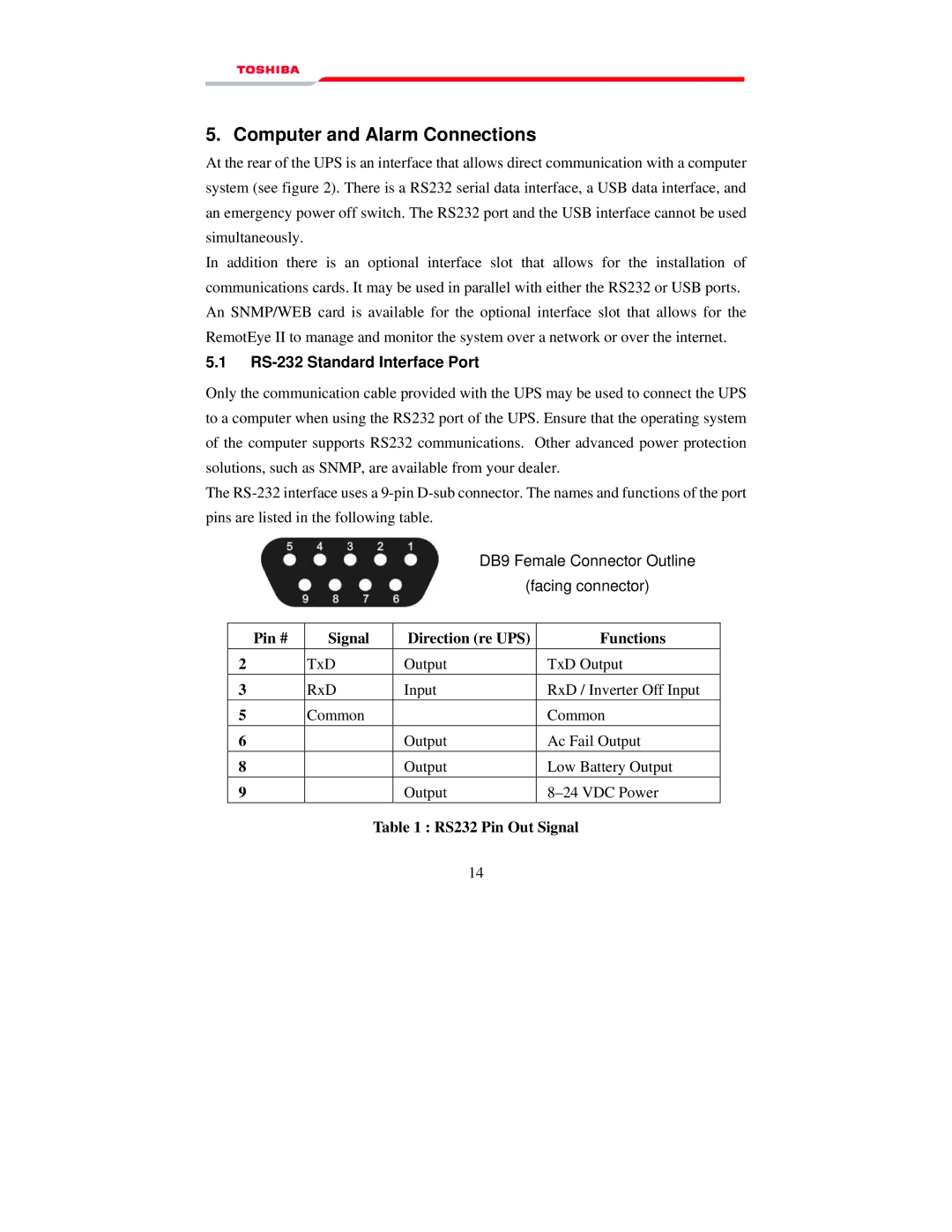
| DB9 Female Connector Outline | |
|
| (facing connector) | |
|
|
|
|
Pin # | Signal | Direction (re UPS) | Functions |
2 | TxD | Output | TxD Output |
3 | RxD | Input | RxD / Inverter Off Input |
5 | Common |
| Common |
6 |
| Output | Ac Fail Output |
8 |
| Output | Low Battery Output |
9 |
| Output | |
Table 1 : RS232 Pin Out Signal
14